
Being far outside the city, where you rarely see a house with a satellite dish, and there is no way to connect cable television, sometimes you wonder how to make an antenna for a TV with your own hands.
In contact with
Classmates
Indeed, anything can happen to an old antenna. The cable is damaged, the signal is lost, the wire comes loose and you are left without television. The situation is unpleasant, but, as it turns out, it is quite fixable. This problem can be solved if you manage to build an indoor antenna using improvised materials and, perhaps, without even resorting to a soldering iron.
The easiest way to make a TV antenna
Living in an apartment building, we are not immune to problems with the possible lack of TV broadcast. But the problem can be solved quickly and quite effectively. To do this, we need copper wire and a knife. Using a knife, we strip both ends of the wire and tie one of them to the heating battery, and insert the other into the socket of your TV.
We turn it on and check the signal. The central heating radiator extends to the roof, thereby increasing the signal, so we, of course, cannot guarantee a hundred channels, but such an antenna will pick up 5-7 and provide a fairly high-quality display.
TV antenna made of aluminum cans
An ignorant person is unlikely to realize that a do-it-yourself indoor antenna can be made from ordinary beer cans or Coca-Cola cans. Moreover, this method has been known for a very long time. For this we will need the following items:
1. Two aluminum cans.
2. Brass, copper wire or old television cable.
3. Triangular clothes hanger.
4. Soldering iron (for structural strength and signal improvement, but you can do without it).
5. Knife.
6. Electrical tape, scotch tape.
Manufacturing process of a can antenna
We rinse the jars and dry them thoroughly. Then we fix the hangers on the edges so that they fit against the bottom side. It is best to secure the cans using adhesive tape or electrical tape, but you can also use other available means. The banks need to hold up well.
Then, we strip the ends of the wire or cable on both sides and thread their ends through the ears, with the help of which the cans are opened. We press these ears to the lid of the jar and insert the other end of the cable into the connector.
Note!
For structural strength, the wire can be soldered to the can and these places can be insulated.
To increase the number of channels, you need to use jars of larger diameter.
TV Antenna UHF and VHF
If you have some skills in working with a soldering iron, then you can easily assemble an antenna for a TV with your own hands for the decimeter and meter ranges. The design does not require engineering skills and to create it we will need: 1. A copper wire 80 cm long and up to 3 mm in diameter. 2. Double-sided fiberglass. 3. Coaxial cable up to 2 meters long and with a resistance of 75 Ohms. 4. Plug.

The procedure for manufacturing a decimeter antenna
First, you need to find a copper wire with a diameter of 2-3 mm. A single-core cable used when installing electrical wiring is most suitable for this. If you find a stranded wire, you need to separate one core without damaging the insulation. As a last resort, you can use aluminum wire. If there is no insulation on the wiring, then for aesthetics, it can be put into a tube, for example, made of vinyl chloride. Then, make a circle with a diameter of 22 cm from the wire. For the convenience of making such a circle, you can use any container of a similar diameter.
Board assembly
To continue assembling such an antenna for television, you will have to make the board yourself. There is nothing complicated about this. We take a piece of PCB measuring 2.5*3.5 cm and a thickness of 1.5 mm, and place copper wire tracks on its surface, also as indicated in the diagram.

Board assembly diagram
The wire diameter should be within 0.4 mm. It can be attached to the board using glue. To reduce external influence and give our design a beautiful look, we hide our board in a box made of plastic or metal, having previously drilled holes for the ring and cable. After these preparatory works, we begin to assemble the structure.
Assembling the TV antenna structure
We tin the ring ends with solder and put them into our box with the board. Then we bend them at a right angle, bring them to the board and seal them. After this, we turn the board to face the bottom of the box and begin preparing the cable. To do this, install a plug on one end of the cable, and disconnect the other and solder it to the board on the reverse side. We fix one of the ends, the central core, to the right end of the ring, and solder the second to the board of our product. After these manipulations, the design is ready. We insert the plug into the TV socket and configure the channels.
DIY TV antenna for digital television
If you know how to hold a soldering iron and a screwdriver in your hands, you can make an antenna for digital television at home, which will be of better quality than many of the Chinese analogues that have flooded our market and, most importantly, almost free of charge. For this we will need the following items: 1. A board 7 cm wide and 55 cm long. 2. Copper wire, 39 cm long and the diameter of the central core is 4 mm. 3. Self-tapping screws in the amount of 10 pcs. 4. Pencil, ruler, knife. 5. Plug.
First, take a board of the required size and make markings according to the diagram:

Construction order
Dimensions are in inches. To convert to centimeters, multiply by 2.5 and round to the nearest tenth. For example, 2 and 5/8″, when multiplied we get 6.56, rounded to 6.6 cm. Then we cut our wire into 8 parts and get pieces of 37.5 cm. On each piece we make cuts 2 cm long, for connections, and clean them. After this, we cut two more wires of 22 cm each and strip them in the places where connections will be made. We bend the wires, which we previously cut into 37.5 cm, into a V shape so that the distance between the edges is 7.5 cm.
The final stage of antenna assembly
Now, in order for us to get a real television antenna for digital television, we need to complete the assembly correctly. To do this, we need to buy a plug with a coil inside and begin the process of connecting the coil to the cable. The cable is connected to the coil through the lower contacts. After this, we complete the antenna assembly by screwing two wires, 22 cm long, to the central screws. On the other hand, we attach these wires to a plug with a coil, which, in turn, must first be attached to the back side of the strip. That's it, the reel is ready for use.
Frame wave channel
To make such an antenna, take copper wire and bend a frame from it. The side of the frame should be about 10 cm. At the junction of the ends, we tie them using the “pigtail” method. After this, after 2 cm, we begin to twist the same frame, connecting the ends in a similar way.
Note! The number of such squares should be four and they are all on the same wire.
The resulting simple design will allow you to replace a damaged antenna in five minutes and get a fairly high-quality picture on your TV screen. All of the listed methods for assembling antennas with your own hands will allow you not only to take advantage of the inconveniences that arise for a short time, but also to use them for a long time without spending money on buying new devices.
Watch the video on how to make a TV antenna with your own hands:
In contact with
See inaccuracies, incomplete or incorrect information? Do you know how to make an article better?
Would you like to suggest photos on the topic for publication?
Please help us make the site better! Leave a message and your contacts in the comments - we will contact you and together we will make the publication better!
Analogue broadcasting, which was used previously, has been completely discontinued since 2009. Changing the format to digital created the need to use an appropriate receiving device. Digital TV is broadcast in the UHF range, which can accommodate many channels, being compact and of high signal quality. The increased level of transmission reduced the cost of maintaining equipment and made it more resistant to interference, although not all problems were completely solved. In rural areas, signal reception is almost impossible, and in a big city it becomes more difficult due to the ability of reinforced concrete structures of multi-story buildings to screen the signal. For reliable reception, it is quite possible to make an antenna for digital TV with your own hands, since its cost in the store is quite high.
Operating principle of a digital antenna
A digital signal differs from an analog signal in that it transmits not the wave itself, but information about it. That is, it consists of a continuous stream of “coordinates” of points on a specific sine wave graph transmitted by conventional analog devices. This makes it possible to significantly reduce interference and improve the quality of signal transmission, since a failure in the transmission of information does not cause major problems and is easily corrected when the signal is decoded in the receiver. Otherwise, the transmission technology remains the same - electromagnetic oscillations are emitted into space from the transmitter, they are received by antennas in the line of sight, on the contours of which a small voltage appears, which is transmitted to the TV decoding device and converted into image and sound.
To receive decimeter waves, a small antenna size is required, which distinguishes the devices from the previously used huge antennas that filled the roofs of houses. The dimensions of digital antennas are quite compact, so they can be freely placed in an apartment, on a balcony or other place that is convenient for the owner and provides high-quality reception. A homemade antenna has a simple design and is quite accessible to manufacture by people without special training who have only basic knowledge.
Making a loop antenna with your own hands
A round antenna for digital TV has the highest input impedanceA loop antenna is one of the simplest options. At the same time, the resistance to interference of such a device is very high, because the design combines a receiving antenna and an interference filter. The name “frame” speaks of a specific configuration - it is a closed contour in the form of a round or rectangular frame. Made from copper wire. Also, as an option, you can use a piece of antenna cable (RG6), freed from vinyl insulation.
Calculation
To calculate a loop antenna, you only need to determine the length of the wire from which the frame is made. The formula for calculating is as follows:
where LR is the length of the wire in the loop,
f is the wave coefficient, which is the arithmetic mean between the values of the boundaries of the wave range. For example, if broadcasting is carried out in the range 568–720 MHz, then f = 568 + 720 / 2 = 644.
You can find out the required ranges on the websites of transmission companies or from other sources - this information is freely distributed. The starting and ending frequencies are used for the calculation. If there is no final frequency, then the value of f is taken equal to the initial frequency.
Some experts give another version of the formula, according to which the side of the square frame is equal to 0.254 of the wavelength (or f). That is, the value obtained from the calculation using the first formula must be increased by 1.5%. The difference is subtle, but in some cases it is important.
To make the antenna you will need:
- Pliers;
- Ruler;
- Soldering iron;
- A utility knife for stripping insulation (if an antenna cable is used).
Only the most basic tools are listed; depending on the skills and capabilities of the user, other devices that are more suitable for any purpose can be used.
Manufacturing instructions
Making a loop antenna is not difficult at all. You will need to do the following:
- Cut a piece of wire to the required length. Experienced users are advised to first cut a piece a little longer than required by the calculation, so that they can more accurately adjust the length when forming the antenna configuration.
- Give the antenna the required shape. If a round loop is used, then it is necessary to make as even a circle as possible; for a square frame, the length of the sides should be precisely maintained.
- The ends of the frame are connected to the antenna wire from the TV: one end to the braid, the other to the central core. To perform this task, you need a soldering iron or a mounting block with terminal clamps.
- All that remains is to install the device in the most favorable place for reception and adjust the position.
How to make a Kharchenko antenna
 You can make such an antenna yourself for receiving Wi-Fi
 The design was proposed by K.P. Kharchenko in 1961. The main task is to receive television broadcasts, but practice has shown the high suitability and versatility of the invention. Kharchenko's external antenna is shaped like a figure eight with an open middle. It consists of two squares, and the connection to the antenna wire is made at the middle points. Thus, we have a closed coil of thick copper wire having a specific shape. The difference from the frame design is precisely the more complex configuration, which allows for stable and reliable signal reception, noise immunity and reliability. Its peculiarity is its broadband and the ability to receive both television and radio signals. It all depends on the location of the antenna - vertical gives reception of a TV signal, horizontal - radio.
The figure eight shape is not the only possible option; you can increase the number of squares formed. Variants with the formation of circles, triangles, etc. are also known. The figure eight is used due to its ease of manufacture and configuration, as well as the absence of interference.
Calculation
Self-calculation of the Kharchenko antenna is not difficult, but it involves determining many quantities. You will need to calculate the length of the side of the square, the size of the reflector (reflector), the total length of the figure of eight from the top to the bottom point, the size of the gap between the reflector and the antenna, etc. Therefore, the simplest and most reliable solution is to use an online calculator, of which there are many on the Internet. To get a more accurate result, you can try to calculate on several services and compare the data.
Required tools and materials
To assemble the Kharchenko antenna you will need:
- Thick copper wire with a cross section of about 4 mm 2;
- Aluminum plate for reflector (reflector). In its absence, a metal grid (mesh) can be used as a reflector;
- Pliers, hammer, screwdriver;
- Electric drill with a set of drills;
- Soldering iron, terminal block;
- A metal pipe or long wooden bars for making a supporting structure (mast).
There are many design options, for the manufacture of which you can use various additional devices. If necessary, they are involved in work order.
Manufacturing instructions
- According to the calculated data, an eight is made.
- The connection at the middle point is soldered, the second point is tinning for subsequent connection of power.
- Holes are drilled in the reflector plate into which bosses are installed to mount the antenna.
- It is fixed on support bosses, and a wire is soldered to the central points.
- The reflector plate is attached to the mast. For this, screws or clamps are used if it is made of a metal pipe.
- The mast with the antenna is installed in the designated place.
- Connects to the TV and adjusts to the optimal position.
Other options
 Design option for Sotnikov's antenna made of three squares
 The options considered are not the only possible ones. There are many antenna designs for receiving television signals.
The following can be distinguished:
- Three-element wave channel. It is a rather complex structure of a horizontal strip on which two transverse stripes and a T-shaped frame are installed. A variant of this design is a four-element wave channel containing three crossbars and one T-shaped structure.
- Double square (Sotnikov antenna). It has a gain of 10–13 dB, consists of two square frames located parallel and connected to each other by a crossbar. A variant of the design is a triple square, the author of which belongs to the same Sotnikov. The amplification capacity is higher - around 14–15 dB.
- Turkin antenna. The gain of this design is more than 15 dB. It consists of six rings of different diameters, mounted on a horizontal dielectric support rod. The device requires a fairly careful calculation of the diameter of the rings and the distance between them.
Video: How to make an antenna for digital TV with your own hands
The transition of television to a digital format occurred in order to eliminate interference, increase transmission quality, more reliable reception and compact equipment. The need to use your own antenna is due to a large amount of interference or distance from the repeater. In the absence of the possibility of purchasing a factory-made sample, which is quite expensive and is not always available for sale, it is quite possible to make a home-made device, since this is not particularly difficult.
Television today and twenty years ago are two very different things. The number of channels, transmission range, and broadcast format have changed. But, in essence, the principle of transmitting a television signal remains the same. Radio waves of a certain frequency travel through the air; they can be received using an antenna and sent to the TV tuner. We will not consider cable and fiber optic TV signal transmission systems, as well as IPTV (broadcasting via the Internet and SMART TVs).
Just like a couple of decades ago, and today, thrifty owners have a reasonable question: how to make an antenna for a TV with your own hands? And if during the USSR there really was a problem in purchasing a high-quality TV antenna (total shortage), today a TV antenna is made with your own hands solely for reasons of economy.
Options for homemade designs: general principles
Depending on the distance between your TV receiver and the transmitting antenna of the television center, the signal level will change. Another negative factor affecting the quality of television wave propagation is the presence of obstacles. Ideal reception occurs when there is a direct line of sight between the two antennas. That is, you can see the mast of the television center, even through binoculars. If there are buildings or tall trees in the path of the TV signal, there will be no reliable reception. However, waves reflected from other objects can be received by a TV antenna amplifier. If even weak waves do not “break through” to your house, you will have to make a mast. The network of television and radio broadcasting stations is located in such a way that you can receive a signal in any locality.

Beer cans (Pepsi-Cola cans work too)
Why is this material so popular?
- firstly, the missing segment sizes are compensated by a large receiving area: if you unfold the can into a plane, you get a standard sheet;
- secondly, aluminum has excellent conductivity, falling slightly short of copper: accordingly, resistance losses will be minimal;
- thirdly, the aerodynamic shape reduces windage (which is especially important when placed outdoors), and the lightness of the structure does not require particularly strong fastening;
- and, finally, this is an affordable and absolutely free raw material; in addition, lacquered aluminum perfectly resists the influence of moisture.

Before making an antenna out of beer cans, make sure that there are no high-rise buildings between the television center and the reception point that could block the signal.
Despite the relatively high reception quality, this design does not have a high self-gain factor. Connecting a standard amplifier may not have an effect due to the complexity of selecting coefficients.
Necessary materials:
- Two identical liter beer cans, washed and dried. As a last resort, you can use half-liter ones, but the reception range will be reduced.
- Antenna cable RK-75 of the required length (a design with a wiring length of more than 10 meters will most likely not provide reliable reception).
- Antenna plug to match your TV.
- A dielectric fastening bracket for fastening cans: a wooden block, clothes hangers, a plastic pipe (metal-plastic will not work).
- Fastening elements: electrical tape, tape, or plastic clamps.
- Soldering iron, standard solder, flux for soldering aluminum.
- Knife, side cutters, sandpaper.
There is no point in describing formulas for calculating sizes based on the reception frequency; anyway, it will not be possible to change the sizes of the segments. This DIY antenna made from beer cans has been tested many times under various conditions, so we’ll just use a ready-made sample.
We cut the antenna cable. There will be a plug at one end, open the other end so that there is at least 100 mm from the central core to the screen wound into a bundle. To prevent the “bare” braid from being exposed to corrosion, it can be hidden in a heat-shrinkable casing.
We clean the areas for soldering the cable: at the upper ends of the cans. Fine sandpaper is suitable for this.
Stripping is carried out immediately before soldering and to the “bare” metal.
We roll each end of the wire into a ring 3–5 mm in diameter and carefully coat it with solder. Then we screw the resulting terminal to the can using a galvanized self-tapping screw. After that, we clean the joints with flux and solder until the solder “sticks” normally.
We fix the cans (from the point of view of the theory of radio reception, these are now symmetrical vibrators) so that there is exactly 75 mm between the ends with the cable. This is the optimal gap for receiving analog and digital television.

An important step: setting up the product for optimal TV signal reception. Most likely, you know the direction to the broadcast center tower. If not, Yandex cards will help you. Find a television center, your home, and conduct a virtual live broadcast. If you don’t want to bother with azimuth (this is impossible without a compass), determine the direction reference within your visibility zone. For example, a boiler room pipe or another object. For reliable reception, the home TV antenna is positioned strictly perpendicular to the vector to the tower, and horizontally.
If the signal is received reliably, you were lucky the first time. At a considerable distance from the transmitter, you can catch the reflected signal. Even a simple antenna made from cans requires correct orientation in space (although it is not a satellite dish). In an area of uncertain reception, all-wave technology can unexpectedly “shoot” in any direction.
A do-it-yourself “beer” decimeter antenna allows you to confidently catch analogue channels. How to make an antenna for digital TV? No additional secrets. Digital broadcasting is produced in the same range. If you have a DVB-T2 tuner, you can tune in to one or two multiplexes, and receive a free set of Russian channels on beer cans.
Information:
If the signal strength is still not enough, you can make an antenna amplifier yourself.
Typical diagram in the illustration:

However, in order to solder and configure such a device yourself, basic knowledge of radio engineering is required. Still, it’s easier to buy a ready-made device, especially since you’ve already saved on the antenna.
“Eight”, aka rhombus, aka “Z” shaped

Perhaps the most popular design for do-it-yourselfers. This fairly powerful Kharchenko antenna confidently receives meter and decimeter frequencies in analog and digital format. When the question arises: “How to make an antenna with your own hands?”, this option is first of all assumed.
What is its advantage? With compact dimensions, in most cases no amplifier is required. Unless you want to receive a signal on the 1st–3rd floor in a densely built-up microdistrict, where there are dozens of high-rise buildings between you and the television center.
How to make a homemade antenna without complex calculations? For a typical broadcast grid, there is a basic diamond arm size: 140 mm. Distance between wire connection points: 10–15 mm.

Kharchenko's antenna with such dimensions falls right in the middle of the typical broadcast range. If it is necessary to capture other channels (in some regions the grid may operate at non-standard frequencies), a wire structure can be made in several rows. The illustration shows a drawing from Radio magazine from 50 years ago.

Then the meter range was accepted, and the antennas had correspondingly gigantic dimensions. They were made from wire to reduce windage. This manufacturing technology requires patience and a large amount of material. Modern “homemade” people prefer a copper tube or an aluminum plate.

To make an indoor antenna using this technology, all you need is a piece of wire. The device hangs in the window opening (in the direction of the television center) and there is no need to worry about it being bent by the wind. Several diamonds can be made, and the reception range will be significantly expanded. An ideal option for digital television, which you can do yourself at the dacha or in a private home.

We amplify the signal without an amplifier
The reception efficiency (primarily this concerns the option under consideration) can be increased without additional electronics. It is enough to install a reflector or reflective screen. It will return television waves back to the antenna field, almost doubling the level. The canvas is located at a distance of 100 mm on the opposite side of the TV tower. A prerequisite is no electrical contact. Moreover, the reflector does not have to be solid. A series of metal tubes or openwork mesh is sufficient.

You can enhance the effect by using the “double biquadrate” design. The same dimensions apply, but the range remains the same. The extra length simply increases the signal strength.

And finally, the most complex antenna for digital TV that you can make yourself
The log-periodic circuit allows you to get maximum gain without additional circuits.

The principle of operation of the design: in the direction of the signal source there are two conductive busbars, on which perpendicular vibrators are installed in strict sequence. Their length and distance between each other are calculated according to a strict algorithm. An error of 2–5% will lead to complete system inoperability. But a properly assembled antenna will receive analog and digital signals with the highest quality.
Note:
This type of antenna requires careful orientation towards the TV tower.
Can be used with a screen that helps strengthen a weak signal.
Bottom line
Making a homemade antenna is not just about saving money. This is an excellent opportunity to practice radio engineering, without the risk of damaging expensive radio elements and materials. And if your receiving point is located in an unfavorable location, you can always try a different configuration without buying several factory-made antennas.
Video on the topic
Suitable for terrestrial digital television standard DVB-T2. But you don’t have to buy them at all, especially since the cost of the device together with a digital receiver can amount to a decent amount. Moreover, such an antenna must be suitable for the parameters of the frequency range that is used in the area where you live. Otherwise, the multiplex used in the antenna will not receive all available TV channels.
We will tell you how to find out the frequency range of your region and calculate the parameters of the desired antenna. Also, our step-by-step instructions will help you quickly make a high-quality antenna from scrap materials for receiving over-the-air channels of the new digital standard DVB-T2.
For reference:
Multiplex(from English multiplex- mixture, mixed; also mux) - combining television channels into a single digital package for digital television broadcasting
What you need to assemble a digital antenna
How to make your own antenna for digital TV? The main condition for self-assembly of a digital antenna is the use of a wire or tube (copper or aluminum) with a diameter of 3 mm (sectional area slightly less than 6 mm2). It is not always possible to find such material even in specialized hardware and electrical stores. Therefore, from a huge variety of types of homemade antennas, we chose the most optimal and least expensive - using the antenna wire itself as the main material.
When choosing such a cable in a store, you must proceed from the parameters that it must have a characteristic impedance of 75 Ohms, and its cross-section (including the sheath) must be at least 6 mm. It is highly desirable that the central core and shielding braid be copper. Antenna cables with a copper-plated steel center wire are commercially available. This is a budget option and is not very desirable to use.
The antenna itself will require a cable length of about 2 m in total, and to connect to your TV you need to determine the required distance yourself.
In addition to the antenna cable itself, you will need:
- soldering iron with solder and rosin;
- sharp knife with short blade
- pliers with wire cutter function and electrical tape
- sealant or glue gun with the appropriate consumable plastic rods (if you are going to place the antenna outside).
Antenna design features
Most antennas offered on the Internet have an angular design made of copper or aluminum tubes (or thick wires), which works great in open areas with direct visibility of the translator. Another type is based on a circle of antenna cable.
 Both designs do not provide very good reception in dense urban areas or in places closed from the line of sight of the translator.
Our version of the antenna (seen on a popular video hosting site) is focused on both the direct signal and the one reflected from buildings in the city. That is why the design consists of two concentric rings made of antenna cable, which greatly simplifies its manufacture.
 This might be interesting:
How to make an antenna for digital television with your own hands: step-by-step instructions
Before we start cutting and stripping the wire, we need to determine the correct length of cable sections for the components of our antenna. To do this, you need to find out the digital television broadcast frequency in your area. But how to calculate an antenna for digital TV? Go to the official website map.rtrs.rf and find your area of residence. In the left menu, select the “Frequency zones” checkbox. Now, in addition to frequency ranges, the map will display multiplex packages and indicate the number of channels included in them. For example, throughout almost the entire Moscow region, the I-multiplex (RTRS-1) includes 10 channels (they are broadcast on channel 30) and can be caught at a frequency of 546 MHz; the II-multiplex (RTRS-2) also includes 10 channels and is broadcast they are on channel 24 at 498 MHz.
 To calculate the length of cable sections for an antenna based on frequency maps, you need to use the formula for determining the wavelength:
λ=300/F, Where F- frequency of the transmitted signal in MHz.
For example, for a frequency of 546 MHz the wavelength is about 550 mm. It is this length of cable that should be used to obtain the first circle of the antenna.
To receive the second multiplex with a frequency of 498 MHz, the length of the antenna cable must be approx. 600 mm.
 First step- cut the cable into the required lengths. In our case it is 550 and 600 mm. After this, each end of the cable is freed by 15 mm from the outer braid, and the shielding is twisted into a tight pigtail and tinned with a soldering iron. Leave the central part of the wire untouched in the braid. She won't be needed.
Second step- solder the right end of the tinned pigtail of the screen of one wire to the other, then do the same with the left ends of the cable. Do not touch the central wires of the antenna cable. You can even wrap them with electrical tape to prevent the ends from touching each other. 
Thus, the base of our concentric antenna is made.
Third step- roll both segments into rings and place them concentrically, i.e. one ring inside the other, for example, on a cardboard from under shoes and secure closer to the ends with packing wires.  The only thing left to do is connect the antenna cable leading to your TV and insulate the exposed contacts.
Fourth step- take your antenna cable of the required length, strip both ends of it from the outer braid by about 15 mm. Clean the end of the cable leading to the antenna in a special way: twist the shielding cable braid into a tight braid and tin it. 
And strip the central wire of the remaining braid by 10 mm, leaving about 5 mm of braid to protect it from a short circuit with the screen wire. 
Fifth step- bring the antenna cable with prepared ends to the previously obtained antenna from concentric rings and twist the end of the braid from it with the end from the left side of the antenna, solder the resulting connection.
Sixth step- insulation of exposed wires. For these purposes, you can use electrical tape or a glue gun (if you have one). Twist the second wire - the central core of the cable - with the end of the braid on the right side of the antenna and solder the connection. This way you will have the shield braid soldered to the left side of the ring and the center core to the right side of the circuit.
Seventh step- connecting the cable to the antenna plug. To do this, cut the outer plastic sheath of the cable by approximately 15 mm and turn the shielding wire inside out, pulling it over the sheath. Carefully strip the central core by 10 mm. Insert it into the central part of the plug (if the design allows), and then screw the outer shielding nut so that it tightly covers the shielding part of the wire. The remaining screen can be carefully cut off.
Thus, our universal dual-band antenna is ready for indoor use. The antenna does not require amplification or additional power supplies. But in dense urban areas, the question still remains of how to properly install an antenna for digital television. To do this, try to experimentally determine the location of the best reception.
 If your TV is not equipped with a modern receiver for receiving terrestrial digital television of the DVB-T2 standard, you will need to purchase this unit. You can read which one works best in.

Despite the rapid development of the Internet, television remains the main source of information for the majority of the population. But in order for your TV to have a high-quality picture, you need a good antenna. It is not at all necessary to buy a television antenna in a store, because you can make it yourself and save a lot of money.
You can find out how to make high-quality antennas for various broadcast bands and what materials to use by reading our article.
There are many types and forms of television antennas, the main ones are listed below:

- Antennas for receiving a “wave channel”.

- Antennas receiving a “traveling wave”.

- Loop antennas.

- Zigzag antennas.

- Log-periodic antennas.
 Array antennas
 - Array antennas.
Antennas for digital television reception
The whole world, including our country, has switched from analogue to digital broadcasting. Therefore, when making an antenna with your own hands or buying it in a store, you need to know which antenna is best suited for receiving DVB-T2 format:

- Indoor antenna- suitable for receiving a signal in DVB-T2 format only at a distance of up to 10 kilometers from the repeater. In principle, at this distance, even an ordinary bare wire inserted into the antenna connector of the TV and directed in the desired direction can receive the signal, but for a more stable and stable signal, it is better to use an indoor antenna.

- Crow antenna- capable of receiving a digital signal at a distance of up to 30 kilometers. This type of antenna is installed outside the home and does not require a clear focus on the repeater. But in cases where the distance from the signal source is more than 30 kilometers or there are interference generators nearby, it is advisable to point the antenna at the TV tower.

- Antenna type DIPOL 19/21-69- receives a signal at a distance of up to 50 kilometers. Requires installation at a height of 8-10 meters and a clear direction to the signal source. In conjunction with an amplifier, it is capable of receiving a digital signal at a distance of up to 80-100 kilometers. The excellent characteristics of this antenna make it one of the best options for receiving a signal in the DVB-T2 format at a remote distance from the repeater.
If you live not far from a TV tower, then you can easily make a simple antenna for receiving a signal in DVB-T2 format with your own hands:
- Measure 15 centimeters of the antenna cable from the connector.
- Remove 13 centimeters of outer insulation and braid from the cut edge, leaving only the copper rod.
- Referring to the TV picture, point the rod in the desired direction.
The antenna is ready! It should be noted that such a primitive antenna is not capable of providing a high-quality and stable signal at a distance from the TV tower and in places with sources of interference.
DIY antennas
Let's look at several options for television antennas that you can make yourself from scrap materials:
Beer can antenna
An antenna from beer cans can be made in literally half an hour, using the materials you have on hand. Of course, such an antenna will not provide a super-stable signal, but for temporary use in a country house or in a rented apartment it is quite suitable.
 Beer can antenna
 To make an antenna you will need:
- Two aluminum cans of beer or other drink.
- Five meters of television cable.
- Plug.
- Two screws.
- A wooden or plastic base on which the jars will be attached (many people use a wooden hanger or mop).
- Knife, pliers, screwdriver, insulating tape.
After making sure that you have all the above items in stock, do the following:
- Strip one end of the cable and attach the plug to it.
- Take the other end of the cable and remove 10 centimeters of insulation from it.
- Unravel the braid and twist it into a cord.
- Remove the plastic layer from the insulating rod of the cable to a distance of one centimeter.
- Take the jars and screw the screws into them in the center of the bottom or lid.
- Attach a rod to one can and a braided cable cord to the other, screwing them onto screws.
- Attach the jars to the base using electrical tape.
- Attach the cable to the base.
- Insert the plug into the TV.
- Moving around the room, determine the location of the best signal reception and attach the antenna there.
There are other variations of this antenna, with four and even eight banks, but no obvious effect of the number of banks on the signal quality has been identified.
You can also learn how to make an antenna from beer cans from the video:
Kharchenko zigzag antenna
The antenna received its name in 1961, after the name of its inventor Kharchenko K.P., who proposed using zigzag-shaped antennas to receive television broadcasts. This antenna is very well suited for receiving digital signals.
 Antenna Kharchenko
 To make a zigzag antenna you will need:
- Copper wire with a diameter of 3-5 mm.
- TV cable 3-5 meters.
- Solder.
- Soldering iron.
- Plug.
- Insulating tape.
- A piece of plastic or plywood for the base.
- Fastening bolts.
First you need to make an antenna frame. To do this, take the wire and cut off a piece of 109 centimeters. Next, we bend the wire so that we get a frame of two parallel rhombuses, each side of the rhombus should be 13.5 centimeters, make loops from the remaining centimeter to fasten the wire. Using a soldering iron and solder, connect the ends of the wire and close the frame.
Take the cable and strip its end so that you can solder the rod and cable shield to the frame. Next, solder the rod and cable shield in the center of the frame. Please note that the screen and the rod should not touch.
Place the frame on the base. The distance between the corners of the frame at the junction with the cable should be two centimeters. Make the size of the base approximately 10 by 10 centimeters.
Strip the other end of the cable and install the plug.
If necessary, attach the antenna base to a stand for further installation on the roof.
You can watch more detailed instructions for making the Kharchenko antenna in the video:
Coaxial cable antenna
To make the antenna you will need a 75 ohm coaxial cable with a standard connector. To calculate the cable length required for the antenna, you need to find out the digital broadcasting frequency and divide it in megahertz by 7500, and round the resulting amount.
 Cable antenna
 Once you have the cable length, do the following:
- Strip the cable on one side and insert it into the antenna connector.
- Step back two centimeters from the edge of the connector and make a mark from which you will measure the length of the antenna.
- Having measured the desired length, bite off the excess with pliers.
- In the area of the mark, remove the insulation and braiding of the cable, leaving only the inner insulation.
- Bend the cleaned part at an angle of 90 degrees.
- Set up your TV with a new antenna.
You can visually consolidate the information by watching the video:
Satellite antenna
It’s worth mentioning right away that to receive a satellite signal you need a tuner and a special set-top box. Therefore, if you do not have this equipment, then creating a satellite dish with your own hands will not be possible, since you yourself can only make a parabolic reflector:

- Plexiglas parabola- produced by heating. The plexiglass is placed on a blank that follows the shape of a parabolic reflector and placed in a chamber with a high temperature. After the plexiglass softens, it takes the form of a blank. After the plexiglass has cooled, it is pulled out of the mold and covered with foil. The disadvantage of such production of a homemade parabola is that the costs of its production exceed the market value of a factory reflector.
- Sheet metal reflector- made from a sheet of galvanized iron, meter by meter in size. The leaf is given a round shape and cuts are made from the edge to the center in the shape of the petals. After this, the sheet is placed on the curved reflector template and the “petals” are fastened with spot welding or rivets.
- Mesh reflector- made from frame and mesh. First, a template is made, the parameters of which are calculated using the formula. Radial parabolas are made from copper wire using a template. The wire cross-section is selected based on the antenna diameter. For example, for an antenna with a diameter of 1.5 meters, use a wire with a diameter of 4-5 mm. It is also necessary to make circular belts. The diameter of the belts changes in increments of 10-30 cm. After making the frame, it is covered with fine copper mesh.
All of the methods listed above can be considered seriously only out of sporting interest, since making a parabolic reflector by hand is a very labor-intensive and expensive process. In addition, it is very difficult to accurately calculate the parameters of a satellite dish at home. Therefore, we advise you not to be original and buy a complete satellite dish.
Antenna amplifier
If the place where you live has a weak television signal and a conventional antenna cannot provide a high-quality picture on your TV, then an antenna amplifier can help in this situation. You can make it yourself if you have a little knowledge of radio electronics and know how to solder. 
Amplifiers should be installed as close to the antenna as possible. It is better to power the antenna amplifier via a coaxial cable through a decoupler.
 Isolation power circuit
 The decoupler is installed at the bottom of the TV and is supplied with 12 volt power from the adapter. Two-stage amplifiers consume a current of no more than 50 milliamps; for this reason, the power of the power supply should not exceed 10 watts.
All connections of the antenna amplifier on the mast must be made by soldering, since the installation of mechanical connections will lead to their corrosion and rupture during further operation in an aggressive external environment.
There are times when you have to receive and amplify a weak signal in the presence of powerful signals from other sources. In this case, both weak and strong signals arrive at the amplifier input. This leads to blocking the operation of the amplifier or switching it to a non-linear mode, mixing both signals, which is expressed in the overlay of the image from one channel to another. Reducing the amplifier supply voltage will help correct the situation.
Please note that UHF amplifiers are greatly influenced by signals in the meter range. To weaken the impact of meter signals, a high-pass filter is placed in front of the UHF amplifier, which blocks meter waves and transmits only signals in the decimeter range.
Below is a diagram of a VHF antenna amplifier:
 VHF antenna amplifier circuit
 - The gain is 25 dB. at a voltage of 12.6 volts.
- Current consumption is no more than 20 milliamps.
- The back-to-back connection of diodes D1 and D2 protects the transistor from failure due to a lightning strike.
- The cascades have a common emitter.
- Capacitor C6 provides correction for the constant response of the amplifier in the high frequency region.
- To stabilize the transistor mode, the amplifier is covered by negative feedback from the emitter of the second transistor to the base of the first.
- To avoid self-excitation of the amplifier, an isolation filter R4 C1 is used.
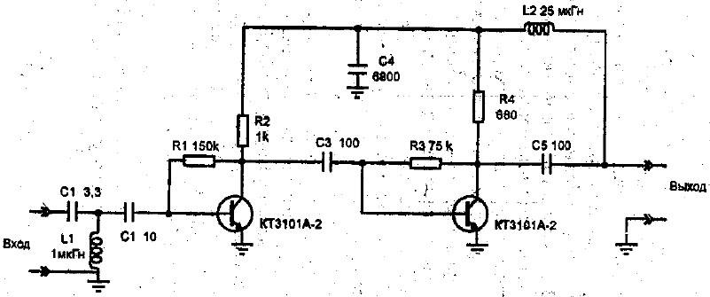
We also suggest that you familiarize yourself with the circuit of the decimeter amplifier:
 UHF amplifier circuit
 - Antenna amplifier of the UHF range 470-790 megahertz.
- Gain 30 dB. at a voltage of 12 volts.
- Current consumption is 12 milliamps.
- The cascades have a common emitter and microwave transistors with a low intrinsic noise level.
- Resistors R1 and R3 provide temperature compensation for the transistor mode.
- The amplifier is powered via a coaxial cable.
You can see the operating principle of the antenna amplifier in the video:
Now, having familiarized yourself with the diagrams and armed with a soldering iron, you can safely begin making an antenna amplifier.
We hope that our article about television antennas was useful to you!