
Paris?! Took!
Washington?! Took!
And after you climbed there, the receiver stopped receiving distant radio stations, my father told me as a child.
Several decades have passed since then, and the receiver, as if nothing had happened, continues to take cities. To be honest, I didn't do anything with the receiver. These Soviet lamp units will work after the apocalypse. It's just the antenna.
Late in the evening, in the reflections of the flames of the fireplace, without turning on the electricity, I press the key of the old tube radio, the luminous scale with cities comfortably saturates the twilight of the room, turning the vernier, I tune in to the radio stations.
The longwave range is silent. True, exactly in the rectangle of the scale of the luminous window of the city of Warsaw at a frequency of about 1300 meters, the radio station "Polish Radio" was taken, and this is a range in a straight line of more than 1150 km.
Medium waves are taken by local and distant radio stations. And here a range of more than 2000 km is taken.
For almost 2 years in Moscow and the region on these waves (DV, SV) the central broadcasting channels have stopped working.
Short waves are especially alive, there is a full house here. At short wavelengths, radio waves are able to go around the Earth and radio stations can actually receive from anywhere in the world, but the conditions for the propagation of radio waves here depend on the time and state of the ionosphere from which they are able to be reflected.
I turn on the table lamp and on all bands (except for VHF), instead of radio stations, there is continuous noise, turning into a rumble. Now the table lamp, including the mains wires, is an interference transmitter that interferes with normal radio reception. Fashionable, at present, energy-saving lamps and other household appliances (TVs, computers) have turned network wires into interference transmitter antennas. It was only necessary to move the network wire from the lamp a couple of meters away from the antenna lowering wire, as the reception of radio stations resumed.
The problem of noise immunity was also in the last century, and in the range of meter waves it was solved by various antenna designs, which were called “anti-noise” antennas.
Anti-noise antennas.
I first read the description of anti-noise antennas in the Radio Front magazine for 1938 (23, 24).
 |
| Rice. 2. |
 |
| Rice. 3. |
A similar description of the design of an anti-noise antenna in the Radiofront magazine for 1939 (06). But here good results were obtained in the range of long waves. The amount of interference attenuation was 60 dB. This article may be of interest to amateur radio communications on the LW (136 kHz).
True, at present the best results are obtained when using a matching amplifier directly in the antenna, which is connected via a coaxial cable to a matching amplifier at the input of the receiver itself.
Antenna whisk.
This was my first homemade antenna, which I made for a detector receiver. The first antenna, about which I burned myself, tinning each wire, strictly according to the drawing, using a protractor, setting the angles of inclination of the twigs. No matter how hard I tried, the detector receiver did not work with her. If I then put a saucepan lid instead of a whisk, the effect would be similar. Then, in childhood, the receiver was saved by network wiring, one wire of which was connected to the detector input through a separating capacitor. That's when I realized that for the normal operation of the receiver, the length of the antenna wire must be at least 20 meters, and all sorts of electron clouds there, conducting layers of air above the panicle, let them remain in theory. Old-timers will still remember that the panicle attached to the chimney caught exceptionally well when the smoke went vertically up. In the villages, they usually stoked the stove in the evening and cooked dinner in cast-iron pots. By the evening, as a rule, the wind subsides, and smoke rises in a column. At the same time, in the evening, waves are refracted from the ionized layer of the earth's surface, and reception in these wave bands improves.
The best results can be obtained with the antenna pictures below (Figure 5 - 6). These are also antennas with concentrated capacitance. Here the wire frame and spiral includes 15 - 20 meters of wire. If the roof is high enough and not made of metal and freely transmits radio waves, then such compositions (Fig. 5, 6) can be placed in the attic.
 |
| Rice. 5. "Radio to everyone" 1929 No. 11 |
 |
| Rice. 6. "Radio to everyone" 1929 No. 11 |
Roulette antenna.
I used an ordinary construction tape measure with a steel sheet length of 5 meters. Such a tape measure is very convenient as a HF antenna, as it has a metal clip electrically connected to the tape web through a shaft. HF pocket receivers have a purely symbolic whip antenna, otherwise they would not fit in a pocket. As soon as I fixed the tape measure on the whip antenna of the receiver, the shortwave bands in the region of 13 meters began to choke from a large number of received radio stations.
Reception on the lighting network.
This is the title of an article in the Radio Amateur Magazine for 1924, No. 03. Now these antennas have gone down in history, but if necessary, network wires can still be used in some lost village, having previously turned off all modern household appliances.Homemade G - shaped antenna.
These antennas are shown in Figure 4. a, b). The horizontal part of the antenna should not exceed 20 meters, usually 8 - 12 meters are recommended. Distance from the ground at least 10 meters. A further increase in the height of the antenna suspension leads to an increase in atmospheric noise.
I made this antenna from a network carrier on a reel. Such an antenna (Fig. 8) is very easy to deploy in the field. By the way, the detector receiver worked well with her. In the figure, which shows a detector receiver, an oscillatory circuit is made from one network reel (2), and the second network extension cable (1) is used as an L-shaped antenna.
Frame antennas.
The antenna can be made in the form of a frame, and is an input tunable oscillatory circuit, which has directional properties, which significantly reduces radio interference.Magnetic antenna.
In its manufacture, a ferrite cylindrical rod is used, as well as a rectangular rod, which takes up less space in a pocket radio. An input tunable circuit is placed on the rod. The advantage of magnetic antennas is their small dimensions, and the high quality factor of the circuit, and, as a result, high selectivity (detuning from neighboring stations), which, together with the directional property of the antenna, will only add one more advantage, such as better reception noise immunity in the city. The use of magnetic antennas is largely intended for receiving local broadcasting stations, however, the high sensitivity of modern receivers in the LW, MW and HF bands and the positive properties of the antenna listed above provide a good radio reception range.
So, for example, I was able to catch a distant radio station with a magnetic antenna, but as soon as I connected an additional bulky external antenna, the station was lost in the noise of atmospheric interference.
 |
| The magnetic antenna in the stationary receiver has a rotary device. |
On a flat ferrite (similar in length cylindrical) rod measuring 3 X 20 X 115 mm brand 400NN for the DV and SV ranges on a movable paper frame, coils are wound with wire of the brand PELSHO, PEL 0.1 - 0.14, 190 and 65 turns each.
For the HF range, the loop coil is placed on a dielectric frame 1.5 - 2 mm thick and contains 6 turns wound in increments (with a distance between the turns) with a loop length of 10 mm. Wire diameter 0.3 - 0.4 mm. The frame with coils is attached at the very end of the rod.
Attic antennas.
I have been using the attic for television and radio antennas for a long time. Here, far from the electrical wiring, the antenna of the MW and HF bands also works well. The roof of the soft roof, ondulin, slate is transparent to radio waves. The magazine "Radio to all" for 1927 (04) gives a description of such antennas. The author of the article “Attic antennas” S. N. Bronstein recommends: “The form can be very diverse, depending on the size of the room. The total length of the wiring should be at least 40 - 50 meters. The material is an antenna cord or bell wire, fixed on insulators. The lightning switch with such an antenna disappears.
I used wire, both solid and stranded from electrical wiring, without removing the insulation from it.
Ceiling antenna.
This is the same antenna on which the father's receiver took cities. Copper winding wire with a diameter of 0.5 - 0.7 mm was wound around a pencil, and then stretched under the ceiling of the room. There was a brick house and a high floor, and the receiver worked perfectly, and when they moved to a reinforced concrete house, the reinforcing mesh of the house became a barrier to radio waves, and the radio stopped working normally.
From the history of antennas.
Going back in time, I was interested to know what the world's first antenna looked like.
The first antenna was proposed by A. S. Popov in 1895, it was a long thin wire raised with balloons. It was attached to a lightning detector (a receiver that registers lightning discharges), a prototype of the radiotelegraph. And during the world's first radio broadcast in 1896 at a meeting of the Russian Physical and Chemical Society in the physics room of St. Petersburg University, a thin wire was stretched from the first radiotelegraph radio receiver to a vertical antenna (Radio magazine 1946 04 05 "First Antenna").
 |
| Rice. 13. The first antenna. |
The frequency range of 1-30 MHz is traditionally called shortwave. On short waves, you can receive radio stations located thousands of kilometers away.
Which antenna to choose for shortwave reception
No matter which antenna you choose, it is best that it be external(on the street), the most highly located and was away from power lines and a metal roof (to reduce interference).
Why is the outside better than the room? In a modern apartment and apartment building there are many sources of electromagnetic fields, which are such a strong source of interference that often the receiver receives only interference. Naturally, the external one (even on the balcony) will be less affected by these interferences. In addition, reinforced concrete buildings shield radio waves, and therefore the useful signal will be weaker indoors.
Always use coaxial cable to connect the antenna to the receiver, this will also reduce the level of interference.
Receiving Antenna Type
In fact, on the HF band, the type of receiving antenna is not so critical. Usually a wire 10-30 meters long is enough, and the coaxial cable can be connected in any convenient place on the antenna, although to provide more broadband (multi-band), it is better to connect the cable closer to the middle of the wire (you get a T-antenna with shielded reduction). In this case, the braid of the coaxial cable is not connected to the antenna.
Wire Antennas
Although more long antennas can receive more signals, they will also receive more interference. This somewhat equalizes them with short antennas. In addition, long antennas overload (there are “phantom” signals over the entire range, the so-called intermodulation) of household and portable radio receivers with strong signals from radio stations, because. they are small compared to amateur or professional radios. In this case, the attenuator must be turned on in the radio receiver (set the switch to the LOCAL position).
If you are using a long wire and connecting to the end of the antenna, it would be better to use a 9:1 matching transformer (balun) to connect the coaxial cable, because. The “long wire” has a high active resistance (about 500 ohms) and such matching reduces the losses on the reflected signal.


Matching transformer WR LWA-0130, ratio 9:1
active antenna
If you do not have the opportunity to hang an external antenna, then you can use an active antenna. active antenna- this is, as a rule, a device that combines a loop antenna (or a ferrite or telescopic one), a broadband low-noise high-frequency amplifier and a preselector (a good active HF antenna costs over 5,000 rubles, although it makes no sense to buy an expensive one for household radios, something like Degen DE31MS). To reduce interference from the mains, it is better to choose an active battery-powered antenna.
The point of an active antenna is to suppress interference as much as possible and amplify the useful signal at the RF (radio frequency) level without resorting to conversions.
In addition to the active antenna, you can use any indoor antenna that you can make (wire, frame or ferrite). In reinforced concrete houses, the indoor antenna should be located away from the electrical wiring, closer to the window (preferably on the balcony).
Magnetic antenna
Magnetic antennas (frame or ferrite), to one extent or another, under favorable circumstances, can reduce the level of "urban noise" (or rather, increase the signal-to-noise ratio) due to their directional properties. Moreover, the magnetic antenna does not receive the electrical component of the electromagnetic field, which also reduces the level of interference.

By the way, EXPERIMENT is the basis of amateur radio. External conditions play a significant role in the propagation of radio waves. What works well for one radio amateur may not work at all for another. The most illustrative experiment on the propagation of radio waves can be carried out with a television decimeter antenna. Rotating it around the vertical axis, you can see that the highest quality image does not always correspond to the direction to the television center. This is due to the fact that during propagation, radio waves are reflected and “mixed with others” (interference occurs) and the most “high-quality” signal comes with a reflected wave, and not with a direct one.
grounding
Don't forget about grounding(through the heating pipe). Do not ground to the protective conductor (PE) in the socket. Old tube radios especially “love” grounding.

Izoshutka
Fighting radio interference
In addition to everything, to combat interference and overloads, you can use preselector(antenna tuner). Using this device allows you to suppress out-of-band interference and strong signals to a certain extent.
Unfortunately, in the city, all these tricks may not give the desired result. When you turn on the radio, only noise is heard (as a rule, the noise is stronger in the low frequency ranges). Sometimes novice radio observers even suspect their radios of malfunction or unworthy characteristics. Checking the receiver is easy. Disconnect the antenna (fold the telescopic antenna or switch to an external one, but do not attach it) and read the S-meter. After that, extend the telescopic antenna or connect an external one. If the S-meter reading has increased significantly, then everything is in order with the radio, and you are out of luck with the reception place. If the interference level is close to 9 points or higher, normal reception will not be possible.
Finding and eliminating the source of interference
Alas, the city is full of “broadband” interference. Many sources generate broad spectrum electromagnetic waves, like a spark discharge. Typical representatives: switching power supplies, collector motors, cars, electric lighting networks, cable TV networks and the Internet, Wi-Fi routers, ADSL modems, industrial equipment and much more.
The easiest way to "search" for the source of interference is to survey the room with a pocket radio (no matter what band, LW-MW or HF, just not the FM band). Walking around the room, you can easily notice that in some places the receiver makes more noise - this is the “location” of the interference source. “Noisy” will be almost everything connected to the network (computers, energy-saving lamps, network wires, chargers, etc.), as well as the wiring itself.
It was in order to somehow reduce the harmful effects of urban interference that “super-duper” fancy radios and transceivers became popular. An urban radio amateur simply cannot work comfortably on household equipment that shows itself worthy “in nature”. Greater selectivity and dynamics are required, and digital signal processing (DSP) allows you to "work wonders" (for example, suppress tonal noise) that analog methods cannot.
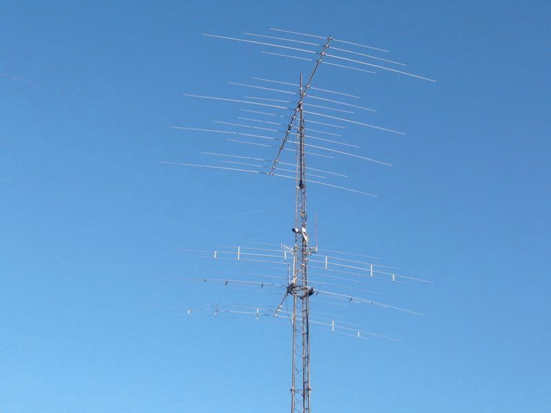
Of course, the best HF antenna is directional (wave channel, QUARD, traveling wave antennas, etc.). But let's be realistic. Building a directional antenna, even a simple one, is quite difficult and expensive.
This antenna is my first development to be published in Radio magazine. It was many, many years ago, back in 1988. At that time, Radio was the only magazine for radio amateurs in the USSR, the queue for publication was about three years. So this loop antenna was actually designed and manufactured in 1985-86. I don't remember the exact date now.
Although the publication was in the "Sports Equipment" section, the main goal of the development was to improve the quality, and most often even just the ability to receive "enemy voices from behind a hillock." In the era of the internet and smartphones, it's hard to believe that HF radio was once the only alternative source of information that didn't pass political censorship.
There was a whole network of jammers that pounced like a pack of wolves on the Voice of America, Radio Liberty and other stations. It was almost impossible to disassemble something in such conditions on the "VEF" or "Ocean" with a standard telescopic antenna. But on this frame, under favorable circumstances, it was possible to accept something.
In those years, even the very existence of broadcast bands 19, 16, 13 and 11 meters was almost a state secret. Only happy owners of imported radio receiving equipment knew about their existence, and, of course, radio amateurs.
Under such conditions, it was absolutely unrealistic to publish a description of an antenna for receiving enemy voices, which the state spent a lot of money on jamming. That's why I focused on amateur bands. I think the editors of the magazine understood this very well, but perestroika had already begun ... In general, this was my very first publication in a reputable radio engineering magazine.
To my great surprise, this design is not forgotten even after 30 years. Reprints from the journal article can be found on several websites. In recent experiments with the SDR receiver, I needed an indoor antenna. After a long search, I nevertheless returned to this old scheme of mine, I could not find anything better. There are not so many new circuit solutions in antenna technology.
But, it should be noted that in the 80s of the last century, thyristor dimmers were the strongest sources of interference in a city apartment (fortunately, there were few of them). Today the situation has changed for the worse. Switching power supplies, digital technology, computers and other charms, which are now indispensable, have led to severe pollution of the electromagnetic environment.
As a result, on HF, reception on an indoor antenna became almost impossible. If 30 years ago I confidently received in the range of 10 m on this antenna in a reinforced concrete house the signals of the satellites of the Radio series, now I was able to receive only the most powerful broadcasting stations.

However, in rural areas and in nature, the antenna can be very useful and effective. That's why I post it on my site. The original text of the article and the original drawings are, unfortunately, lost. Therefore, I have no choice but to use the materials of the journal publication, adding a few of my comments to the text.
Shortwave observers often do not have the opportunity to use an external antenna and in such cases are forced to be content with a room one. And if a radio amateur lives in a city apartment, then the antenna often turns out to be, as it were, in a shielded chamber formed by concrete reinforcement. This not only attenuates useful signals, but also enhances local noise fields. In such a situation, it is advisable to use an antenna with minimal sensitivity to interference, placing it in a window opening or on a balcony.
One possible solution to this problem is the use of small loop antennas, the perimeter of which does not exceed a quarter of a wavelength. Such antennas are already widely used as transceivers in amateur radio stations. The presence of a pronounced minimum in the radiation pattern of the frame makes it possible in some cases to reduce interference. By changing the position of the antenna in the vertical and horizontal planes, it is possible to improve the quality of reception even if the signal and interference come from the same direction, but at different angles to the horizon. In some cases, using a loop antenna, using component selection methods, it is possible to increase the noise immunity and real selectivity of the radio receiver near interference sources. In addition, since such an antenna does not require the use of grounding, the likelihood of a multiplicative background is reduced, and due to its tuning to resonance, the selectivity of the receiver for the mirror and other side channels increases.
The antenna described below is designed to work with any amateur receiver in the 3.5, 7, 14, 21 and 28 MHz bands. Thanks to its minimum beam pattern, it attenuates the interfering signal by 26 dB at 28 MHz and by 20 dB at 3.5 MHz. The frame with a diameter of 300 mm is made of a television coaxial cable. The frequency dependence of its quality factor and the effective height is shown in Fig.1.
In order to increase the signal-to-noise ratio in the receiving system, the frame is structurally combined with an amplifier, the use of which also facilitates its balancing and matching with the receiver. The circuit diagram of the amplifier is shown in fig. 2. The range of its operating frequencies according to the level of -3 dB is not less than 3 ... 30 MHz. Voltage gain - 12 dB. The noise level at the output in the 3 kHz band at a load of 75 ohms does not exceed 0.3 μV. Dynamic range - not less than 90 dB. Load resistance - 75 Ohm. The amplifier is powered from a 9 V source. The current consumption is 8 mA.
In reality, the frame covered the frequency range from approximately 5.8 to 30 MHz, i.e. broadcast and amateur bands from 49 to 10 m. On 80 m, a single-turn frame with a diameter of 30 cm is, of course, ineffective. Do not judge strictly by the above figures, they do not claim to be absolute accuracy, but are close to reality. Even on the circuit diagram in the magazine there was a typo, the source and drain of VT1 were swapped. Here I corrected this typo.


The antenna is tuned to the operating frequency with a double variable capacitor C5. When operating in the range of 3.5 and 7 MHz, additional capacitors C1, C2 and C3, C4 are connected in parallel to its sections, respectively.
The voltage induced in the WA1 frame is fed to the input of the amplifier, the first stage of which is made according to a symmetrical differential circuit on field-effect transistors VT1 and VT2. The high input impedance of the stage practically does not reduce the quality factor of the antenna, and also makes it possible to significantly weaken the direct antenna effect, which distorts the radiation pattern. Inductors L1 and L2 provide suppression of low-frequency pickups.
The output amplifier is assembled on a bipolar transistor VT3, connected according to a common emitter circuit, and is covered by a deep parallel negative voltage feedback through the circuit R2, C10. This made it possible to obtain uniform gain over a wide frequency band, as well as small input and output impedances of the amplifier.
This construction of the device ensured its good linearity and matching with the coaxial cable through which the signal is fed to the input of the receiver. Power is supplied to the amplifier from the receiver via a separate shielded wire.
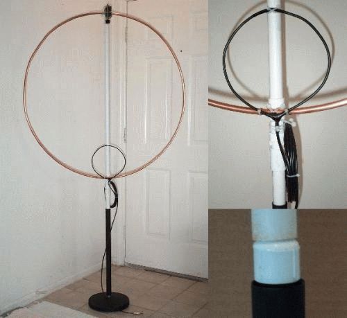
The appearance of the antenna is shown in fig. 3 at the beginning of the page, the placement of elements in the case - in fig. 4.
Frame 2 is made of RK-75-4-15 coaxial cable and is fixed on two cross-shaped spacers 1 and 8 (see drawings in Fig. 5) from any dielectric material (organic glass, plywood, etc.) with wire segments 9 with a diameter of 0.8 mm. In the upper part of the cable, the outer sheath and screen braid 11 are removed at a distance of 10 mm (view A). The inner shell 10 is wrapped in this place with an insulating PVC tape (not shown in Fig. 4).
The body 7 and the front wall 4 are made of brass sheet 0.25 mm thick. Their drawings are shown in Fig. 5. The body can also be soldered from double-sided foil fiberglass with a thickness of 1 mm. The screen braid of the cable is soldered directly to the case. Nut 6 (M9), which is soldered to the end of the housing, is used to mount the antenna on the swivel head of a compact photo tripod. This design makes it easy to change the position of the antenna in space and detune from interference. Tuning knob 5 is made of ebonite.
The amplifier is assembled on a printed circuit board 3 dimensions 75 x 25 mm from foil fiberglass 1 mm thick. A drawing of a printed circuit board and the placement of parts on it are shown in fig. 6.
Currently, when manufacturing an amplifier, it makes sense to modify the board for SMD components
Inductors L1 and L2 are wound on ring magnetic cores of size K7 x 4 x 2 made of ferrite with an initial magnetic permeability of 400 ... 1000 and contain 25 turns of PELSHO 0.12 wire. Transformer T1 is made on the same magnetic circuit. Each of its windings contains 10 turns of wire PEV-2 0.17. Winding is carried out immediately with three wires twisted into a bundle.
KPE C5 - dual block KPTM-4 with a capacity of 7 ... 260 pF from pocket radios "Neiva-401", "Signal-601". With the appropriate adjustment of the printed circuit board, you can use the KPI block from any pocket receiver. All other capacitors - KM; It is desirable to use C1-C4 with a tolerance of at least + - 5%. Switches SA1, SA2 - MT3.
Transistors KP303E can be replaced with KP303G, KP303D, KP302A, KP302B. It is necessary to choose a pair with possibly close parameters. Instead of the GT311Zh transistor, you can use GT311E, GT311I, KT306, KT316, KT325 and other modern microwave transistors.
Now you can find much better imported transistors, with less noise. Google knows the brand of analogues.
The cable connecting the device to the receiver is RK-75-2-11 or any other with a wave impedance of 75 ohms. Its length should not exceed 5 m. Power is supplied to the antenna amplifier from the receiver via a shielded wire of any type.

The antenna begins to be adjusted by setting the transistor modes indicated on the circuit diagram by selecting resistors R1 and R3. Then, the terminals of the capacitor C5 are temporarily connected to a common wire, the amplifier is connected to a receiver operating in the 28 MHz band in SSB mode, and, by selecting the resistor R2, a situation is achieved when the amplifier noise slightly exceeds the receiver noise. After that, using the GIR, the resonant frequency of the frame is determined at the minimum and maximum capacitance of the capacitor C5 (the contacts of the switches SA1 and SA2 are open).

By changing the perimeter of the frame, the frequency range of 14 ... 30 MHz is set with a 5% margin. It is advisable to first take a cable with a length of about 1.2 m, and then shorten it symmetrically at both ends. If the PK-75-4-15 cable and capacitor C5 with a capacity of 7 ... 260 pF are used, the indicated frequency range overlaps with a frame perimeter of about 95 cm, which corresponds to a diameter of 30 cm.
Then close the contacts of the switch SA2. The rotor of the capacitor C5 is set to the middle position and by selecting the capacitors C3 and C4 (they must be of the same rating), resonance is achieved at a frequency of 7.05 MHz. In the 3.5 MHz band, the antenna is tuned in a similar way, selecting capacitors C1 and C2. In this case, contacts SA2 must be open, SA1 - closed.
When SA1 was closed, the antenna covered the ranges of 25-31 m, when SA2 was closed, 40 m, and when both toggle switches were closed, 49 m. Unfortunately, I don’t remember the capacitor values. There is nowhere to look, the original version of the antenna has not been preserved. But picking it up won't be hard.
If there is no GIR, you can tune directly by the signals of amateur radio stations. At resonance, the volume will rise sharply. The advantages of this antenna are most fully manifested if the signals of radio stations do not penetrate the receiver input directly from the air.
Literature:
1. Stepanov B. Shortwave antennas. - In the book: Radio Yearbook, 1985.-M.: DOSAAF USSR, 1985.
2. Grechikhin A. Component selection. - Radio, 1984, No. 3, p. 18-20.
3. Egorov I. Multiplicative background in radio receivers. - Radio, 1980, No. 9, pp. 40-41.
4. Khabarov Yu.E. Shortwave active antenna. - M: Energy, 1977, pp. 21-24.
5. Mishustin I.A. Improving the noise immunity of amateur radio reception. - M: Energy, 1974.
6. Egorov I. On the noise immunity of household radio equipment. - Radio, 1981, No. 7-8, p. 30-31.
The HF band contains a number of radio frequencies (27 MHz, commonly used by drivers), broadcasting many stations. There are no TV shows here. Today we will consider the amateur series involved by various radio enthusiasts. Frequencies 3.7; 7; 14; 21, 28 MHz of the HF band, related as 1: 2: 4: 6: 8. It is important, as we will see later, it becomes possible to make an antenna that would catch all the ratings (the issue of coordination is the tenth thing). We believe that there will always be people who will use the information, catch radio broadcasts. Today's topic is a do-it-yourself HF antenna.
We will disappoint many, today we will again talk about vibrators. The objects of the Universe are formed by vibrations (the views of Nikola Tesla). Life attracts life, it is movement. To give life to a wave, vibrations are necessary. Changes in the electric field generate a response of the magnetic one, so the frequency that carries information to the ether crystallizes. The immobilized field is dead. A permanent magnet will not generate a wave. Figuratively speaking, electricity is masculine, exists only in motion. Magnetism is a rather feminine quality. However, the authors delved into philosophy.
It is considered preferable to use horizontal polarization for transmission. Firstly, the azimuth radiation pattern is not circular (it was said in passing), there will certainly be less interference. We know that various objects like ships, cars, tanks are being equipped for communication. You can not lose commands, orders, words. The object will turn in the wrong direction, but is the polarization horizontal? We disagree with well-known, respected authors who write: vertical polarization was chosen as a connection for an antenna of a simpler design. Touch the matter of amateurs, it is rather about the continuity of the legacy of previous generations.
We add: with horizontal polarization, the parameters of the Earth have less effect on wave propagation, in addition, with vertical polarization, the front suffers attenuation, the lobe rises to 5 - 15 degrees, which is undesirable when transmitting over long distances. For vertically polarized (single-ended) antennas, good grounding is essential. Directly depends on the efficiency of the antenna. It is better to bury wires with a length of the order of a quarter of a wave with earth, the more, the higher the efficiency. Example:
- 2 wires - 12%;
- 15 wires - 46%;
- 60 wires - 64%;
- ∞ wires - 100%.
An increase in the number of wires reduces the wave resistance, approaching the ideal (of the indicated type of vibrator) - 37 Ohm. Note that the quality should not be brought closer to the ideal, 50 ohms do not need to be coordinated with the cable (in connection, PK - 50 is used). Great deal. Let's supplement the package of information with a simple fact, with horizontal polarization, the signal is added to the reflected Earth, giving an increase of 6 dB. Vertical polarization shows so many minuses, they use it (it turned out interesting with the ground wires), they put up with it.
The device of HF antennas is reduced to a simple quarter-wave, half-wave vibrator. The second ones are smaller in size, they accept worse, the second ones are easier to agree on. The masts are placed vertically using spacers, extensions. They described a structure hung on a tree. Not everyone knows: at a distance of half a wave from the antenna there should be no interference. It concerns iron, reinforced concrete structures. Wait a minute to rejoice, at a frequency of 3.7 MHz the distance is ... 40 meters. The antenna is eight stories high. Building a quarter-wave vibrator is not easy.
It is convenient to build a tower to listen to the radio, we decided to recall the old way of catching long waves. You will find internal ferromagnetic antennas in Soviet-era receivers. Let's see if the designs are suitable for their intended purpose (catching the broadcast).
HF Magnetic Antenna
Suppose there is a need to accept frequencies of 3.7 - 7 MHz. Let's see if it is possible to design a magnetic antenna. Formed by a core of round, square, rectangular section. The dimensions are calculated by the formula:
do = 2 √ rs / π;
do is the diameter of the round rod; h, c - height, width of a rectangular section.
Winding is not carried out for the entire length, in fact, you need to calculate how much to wind, choose the type of wire. Let's take an example of an old design textbook, let's try to calculate a 3.7 - 7 MHz HF antenna. Let us take the resistance of the input stage of the receiver 1000 Ohm (in practice, readers measure the input resistance of the receiver on their own), the parameter of the equivalent attenuation of the input circuit, at which the specified selectivity is achieved, der equal to 0.04.
The antenna, which we are designing, is part of the resonant circuit. It turns out a cascade endowed with a certain selectivity. How to solder, think for yourself, just follow the formulas. Those conducting the calculation will need to find the maximum, minimum capacitance of the trimmer capacitor, using the formula: Cmax \u003d K 2 Cmin + Co (K 2 - 1).
K is the subband coefficient, determined by the ratio of the maximum resonant frequency to the minimum. In our case, 7 / 3.7 = 1.9. It is selected from incomprehensible (according to the textbook) considerations, according to the example given by the text, we take equal to 30 pF. Let's not go wrong. Let Cmin = 10 pF, we find the upper limit of the adjustment:
Cmax \u003d 3.58 x 10 + 30 (3.58 - 1) \u003d 35.8 + 77.4 \u003d 110 pF.
Rounded off, of course, you can take a larger range variable capacitor. The example gives 10-365 pF. We calculate the required inductance of the circuit using the formula:
L \u003d 2.53 x 10 4 (K 2 - 1) / (110 - 10) 7 2 \u003d 13.47 μH.
The meaning of the formula is clear, let's add, 7 is the upper limit of the range, expressed in MHz. Selecting the core of the coil. At the frequencies of the range, the magnetic permeability of the core is M = 100, we select the ferrite grade 100NN. We take a standard core 80 mm long, 8 mm in diameter. The ratio l / d \u003d 80 / 8 \u003d 10. From the directories we extract the effective value of the magnetic permeability md. It turns out 41.
We find the winding diameter D = 1.1 d = 8.8, the number of winding turns is determined by the formula:
W = √(L / L1) D md mL pL qL;
formula coefficients are read visually using the graphs below. The figures will show the reference figures used above. Look for the brand of ferrite, a person does not live by bread alone. D is expressed in centimeters. The authors obtained: L1 = 0.001, mL = 0.38, pL = 0.9. qL can be calculated using the formula:
qL = (d / D) 2 = (8 / 8.8) 2 = 0.826.

We substitute the numbers in the final expression for calculating the number of turns of a ferrite HF antenna, it turns out:
W \u003d √ (13.47 / 0.001) x 0.88 x 41 x 0.38 x 0.9 x 0.826 \u003d 373 turns.
The cascade must be connected to the first amplifier of the receiver, bypassing the input circuit. Let's say more, now we have calculated the means of selectivity in the range of 3.7-7 MHz. In addition to the antenna, it turns on the input circuit of the receiver at the same time. Therefore, it will be necessary to calculate the inductance of coupling with the amplifier, fulfilling the conditions for ensuring selectivity (we take typical values).
Lsv \u003d (der - d) Rin / 2 π fmin K 2 \u003d (0.04 - 0.01) 1000 / 2 x 3.14 x 3.7 x 3.61 \u003d 0.35 μH.
The transformation ratio will be m = √ 0.35 / 13.47 = 0.16. We find the number of turns of the communication coil: 373 x 0.16 = 60 turns. We wind the antenna with a PEV-1 wire with a diameter of 0.1 mm, we wind the coil with a PELSHO with a diameter of 0.12 mm.
Many people are probably interested in several questions. For example, the appointment of formulas for calculating a variable capacitor. The author bashfully avoids the question, supposedly the initial capacity of the circuit. Diligent readers will calculate the resonant frequencies of a parallel circuit in which an initial capacitance of 30 pF is soldered. We will make a slight mistake in recommending that a tuning capacitance of 30 pF be placed next to the variable capacitor. The chain is being worked on. Beginners are interested in the electrical circuit, which will include a home-made HF antenna ... The parallel circuit, the signal from which is taken by the transformer, is formed by wound coils. The core is common.
An independent HF antenna is ready. You will find this in a tourist receiver (models with a dynamo are popular today). HF antennas (and even more so MW) would be great if the design was made in the form of a typical vibrator. Such designs are not used by portable equipment. The simplest HF antennas take up a lot of space. Better reception. The purpose of the HF antenna is to improve signal quality. In the apartment, balconies. They told how to make a miniature HF antenna. Use vibrators in the country, in the field, forest, in open areas. The material is provided by the design guide. The book is full of errors, and the result seems to be tolerable.
Even old textbooks sin with misprints missed by editors. It concerns more than one branch of radio electronics.
Did you mean this:
We can say that the 80-meter range is one of the most popular. However, many land plots are too small to install a full-size antenna on this band, which is what American shortwave Joe Everhart, N2CX encountered. Trying to choose the optimal type of small-sized antenna, he analyzed many options. At the same time, classical wire antennas were not forgotten, which, with a length of more than L / 4, work quite efficiently. Unfortunately, these end-fed antennas need a good grounding system. Of course, good grounding is not required in the case of a half-wave antenna, but its length is the same as that of a full-sized dipole fed from the center.
Without exaggeration, we can say that the 80-meter range is one of the most popular. However, many land plots are too small to install a full-size antenna on this band, which is what American shortwave Joe Everhart, N2CX encountered. Trying to choose the optimal type of small-sized antenna, he analyzed many options. At the same time, classical wire antennas were not forgotten, which, with a length of more than L / 4, work quite efficiently. Unfortunately, these end-fed antennas need a good grounding system. Of course, good grounding is not required in the case of a half-wave antenna, but its length is the same as that of a full-sized dipole fed from the center.
So Joe decided that the simplest antenna with good performance was a horizontal dipole excited at the center. Unfortunately, as has already been pointed out, the length of an 80m half-wave dipole is often a hindrance to installation. However, the length can be reduced to about L/4 without fatal performance degradation. And if you raise the center of the dipole and bring the ends of the vibrators closer to the ground, we get the classic Inverted V design, which will further save space during installation. Therefore, the proposed design can be considered as the Inverted V of the 40m band, which is used on 80m (see figure above). The antenna web is formed by two vibrators 10.36 m each, symmetrically descending from the feeding point at an angle of 90° to each other. During installation, the lower ends of the vibrators must be located at a height of at least 2 m above the ground, for which the height of the suspension of the central part must be at least 9 m. The low suspension height causes effective radiation at large angles, which is ideal for communications at distances up to 250 km The most important advantage of this design is the fact that its projection does not exceed 15.5 m.
As you know, the advantage of a center-fed half-wave dipole is good matching with a 50 or 75-ohm coaxial cable without the use of special matching devices. The described antenna in the range of 80 m has a length of L/4 and, therefore, is not resonant. The active component of the input impedance is small, and the reactive component is large. This means that when pairing such an antenna with a coaxial cable, the SWR will be too high, and the loss level will be significant. The problem is solved simply - you need to apply a line with low losses and use an antenna tuner to match it with 50-ohm equipment. A 300 ohm television flat ribbon cable was used as the antenna feeder. A two-wire overhead line provides less losses, but it is more difficult to bring it into the room. In addition, the feeder length may need to be adjusted to fit within the tuning range of the antenna tuner.
In the original design, the end and central insulators were made of 1.6 mm thick fiberglass scraps, and an insulated mounting wire with a diameter of 0.8 mm was used for the antenna web. Small diameter wires have been successfully operated on the N2CX radio for several years. Of course, stronger mounting wires with a diameter of 1.6 ... 2.1 mm will last much longer.
The conductors of a flat television cable are not strong enough and usually break at the points of connection to the antenna tuner, therefore, an adapter made of foil fiberglass provides the necessary mechanical strength and ease of connecting the line to the tuner.
The tuner circuit is very simple, and is a series resonant circuit that provides matching with a coaxial cable.
________________________________________________________
Here's another option:

Short vertical on 80m range
At the end of 2009, Waldek, SP7GXP, designed a shortened vertical antenna for the 80m band. The design consists of a vertical whip radiator mounted on a support insulator and separated at the top by a second insulator. A delta-shaped frame is connected to the emitter, and a half-wave dipole is located below the support insulator as a counterweight.
The dimensions of the listed antenna design elements are:
- the length of the emitter from the support insulator to the upper insulator - 8 m;
- length of the emitter installed on the upper insulator - 3 m;
- frame length for fp = 3.8 MHz - about 7.7 m (for fp = 3.5 MHz - about 9.35 m);
- length of one arm of the dipole (counterweight) for fp = 3.8 MHz - minimum 18.7 m (for fp = 3.5 MHz - minimum 20.35 m);
- the height of the dipole placement above the ground (roof) is at least 2 m.
The frame should be set aside from the vertical emitter. In addition, it serves as two braces for the upper part of the emitter. The length of the RG-58U coaxial cable is at least 26.5 m.
Antenna tuning steps using a transceiver and an SWR meter:
- install the emitter with a frame;
- we stretch the half-wave dipole at a height of at least 2 meters above the surface, but do not connect it to the base of the antenna;
- the power cable is connected to a half-wave dipole;
- turn on the transceiver in the carrier transmission mode and select the dipole length so as to obtain a minimum SWR at a frequency of 3.780 MHz (or another preferred frequency);
- disconnect the power cable from the dipole, connect the ends of the dipole, as well as the screen (braid) of the power cable at one point, below the base insulator (to the roof, ground, etc.);
- we connect the cable core to the emitter;
- turn the transceiver back into transmission mode and, by selecting the length of the frame, tune the antenna system to the required frequency (for example, 3.780 MHz).
In order for the antenna to cover the entire range (CW and SSB sections from 3.5 to 3.8 MHz), 3 coils with switches can be used to obtain the appropriate resonant frequencies of the antenna. The coils are installed at the support insulator and the shoulders of the dipole (counterweight) are connected to two of them, and the vertical emitter is connected to the third. The number of turns of the coil is selected experimentally - depending on the section of the range.
When installing the antenna, the following rules should be observed. If the roof or surface on which the antenna is installed does not allow stretching a full-size dipole in a straight line, you can try to bend its ends (“twist”), always adhering to the requirement to comply with the required installation height (at least 2 m).
To comply with the rules for safe operation of the antenna, the ends of the dipole, ending with insulators, should be removed from metal objects (for example, fences, metal walls, etc.). Do not use any "ground" counterweights or lying on the ground! When mounting the antenna on the ground, the lower part, below the support insulator, must be in contact with the ground, and when mounting on the roof, it is necessary to connect this part of the antenna (below the insulator) to the lightning rod.