
Very often there is a need to control the brightness of the lamp within a certain value, this is usually from 20% to 100%. Setting the brightness less does not make sense, since most lamps simply do not work in this mode or give a meager amount of light that is enough only to glow the lamp, but it will not illuminate anything. You can go to the store and buy a ready-made device, but now the prices for these devices are very high and do not correspond to the product received. Since we are jacks of all trades, we will make these devices ourselves. Today we will consider several schemes, thanks to which it will become clear to you how to make a 12 V and 220 V dimmer with your own hands.
On triac
To begin with, consider the circuit of a dimmer switch operating from a 220 volt network. This type of device works on the principle of phase shift opening the power key. The heart of the dimmer is an RC circuit. The node for the formation of the control pulse, which is a symmetrical dinistor. And actually, the power switch itself, which controls the load, is a triac.
Let's consider how the circuit works. Resistors R1 and R2 form . Since R1 is variable, it changes the voltage in the R2C1 chain. The DB3 dinistor is connected to the point between them, and when the voltage of its opening threshold on the capacitor C1 is reached, it fires and sends a pulse to the power switch - triac VS1. It opens and passes current through itself, thus at the output we get voltage. The position of the regulator determines how much of the wave will go to the lamp. The faster it charges, the faster the key opens, and most of the wave and power will go to the load. Thus, the circuit literally cuts off part of the sinusoid. Below is a graph of the device.

The value (t*) is the time it takes for the capacitor to charge up to the opening threshold of the power element. This dimmer circuit is simple and easy to repeat in practice. It works best on incandescent lamps, due to the fact that the spiral in the lamp has inertia, but problems can arise with LED and other lamps, so it is necessary to check the operation of the circuit specifically for your consumers before final installation. We recommend watching the video below, which clearly shows how to make a dimmer on a triac:
1000W Triac Power Regulator
On thyristors
You can not buy a triac, but make a simple thyristor dimmer, which can be easily obtained from old non-working equipment and boards, like TVs, tape recorders, etc. The circuit is slightly different from the previous one, in that each half-wave has its own thyristor, and thus its own dinistor for each key.
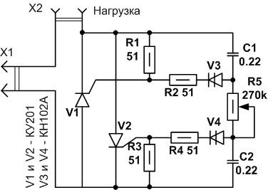
Let us briefly describe the regulation process. During the positive half-wave, the capacitance C1 is charged through the chain R5, R4, R3. When the opening threshold of the dinistor V3 is reached, the current through it enters the control electrode of the thyristor V1. The key opens by passing a positive half-wave through itself. With a negative phase, the thyristor is locked, and the process is repeated for another key V2 and capacitor C2, which is charged through the chain R1, R2, R5.
Phase regulators - dimers can be used not only to adjust the brightness of incandescent lamps, but also to control the speed of the exhaust fan, you can make an attachment for a soldering iron and thus regulate the temperature of its tip to improve soldering quality.
Video assembly instruction:
Assembling a thyristor dimmer
Important! This control method is not suitable for working with fluorescent, economical compact and LED lamps due to the nature of their work.
Condenser dimmer
Along with smooth regulators, capacitor dimmers have become widespread in everyday life. The operation of this device is based on the dependence of the transfer of alternating current on the value of the capacitance. The larger the capacitance of the capacitor, the more current it passes through itself. Thus, with the help of a capacitor, it is possible to reduce the power supplied to the lamp, but this method does not allow smooth adjustment. This type of homemade dimmer can be quite compact, it all depends on the required brightness parameters, and therefore on the capacitance of the capacitor, which is related to its size.

As can be seen from the diagram, there are three positions: 100% power, through a quenching capacitor (power reduction) and off. The device uses a non-polar paper capacitor, which can be obtained from old technology. About that, we told in the corresponding article!
Below is a table relating capacitance and lamp voltage.

Based on this scheme, you can assemble a simple night light yourself and use a toggle switch or switch to control the brightness of the lamp.
On a chip
To regulate the power supplied to the load in 12 volt DC circuits, often use integral stabilizers- Krenki. The use of a microcircuit simplifies the development and installation of devices due to the small number of radio components. Such a homemade dimmer is easy to set up and has some protection features.
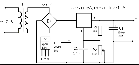
With the help of a variable resistor R2, a reference voltage is created at the control electrode of the microcircuit. Depending on the set parameter, the output value is adjusted from a maximum of 12 V to a minimum of tenths of a Volt. The disadvantage of these regulators is low efficiency and the maximum possible power of the connected load, as a result of this, it is necessary to install an additional radiator for good cooling of the KREN, since part of the energy is released on it in the form of heat. However, it is ideal for low power DC and low voltage circuits due to its simplicity and versatility.
This dimmer was repeated by me and did an excellent job with led strip 12 volts, three meters long and made it possible to adjust the brightness of the LEDs from zero to maximum.
An excellent option is a 555 integrated timer dimmer that controls the KT819G power switch, short PWM pulses. By setting the circuit to a high frequency, you can get rid of flicker, which often occurs due to cheap purchased dimmers and causes rapid fatigue and eye irritation in humans.
In this mode, the transistor is in two states: fully open or fully closed. The voltage drop on it is minimal, which allows you to connect a more powerful load and use a circuit with a small radiator, which compares favorably with the previous circuit with a ROLL regulator in terms of size and economy.
![]()
Making a 12 volt dimmer
That's actually all the ideas for assembling a simple dimmer at home. Now you know how to make a dimmer with your own hands for 220 and 12V.
Repair of a drill can be carried out on your own, the main thing is to know the causes of breakdowns and methods for their “treatment”. Today we will talk about how the drill button connection diagram looks like, we will not ignore other malfunctions, so that you will be the happy owner of a working tool.
If your tool began to work worse, or completely stopped performing its direct duties, it's time to diagnose the malfunctions and try to cope with them. First, we check the wire for damage and the voltage in the outlet, for which you can turn on any other device - a TV or a kettle.
If you are inspecting battery-operated devices, they should be checked using a tester - in this case, the voltage indicated on the case should be the same as the battery voltage.
If the voltage is less, you will have to change the batteries to new ones. If the battery is working normally, the power supply is normal, look for problems in the hardware. The most common breakdowns are:
- Problems with the engine;
- Wear of brushes;
- Problems with the button.
Knowing how the button of the electric drill is connected, you can quickly solve the problem. In addition, a problem with the work of the drill can also arise due to the dust content of the tool, because the drill “takes” wood, brick, and other materials. This means that you should take care to clean the device after each use - this is the only way to reduce the risk of malfunctions due to dirty tools. That is why after you have spent, immediately clean the drill.
Unfortunately, a tester will not be enough for you to check the tool’s performance, which is due to the fact that most of the device’s buttons are equipped with smooth speed control, and therefore a regular tester may give you incorrect data. In this case, you will need a special connection diagram for the drill button. Often in tools, one wire is connected to the terminal, and therefore pressing the button at the same time leads to the terminals ringing. In the event that the light comes on, everything is fine with the button, but if you notice a malfunction, it's time to replace the button.
When replacing, keep in mind that the circuit can be both simple and reverse. Due to this, it is necessary to carry out all work on replacing the button exclusively according to the scheme, without adding anything “from oneself”. So, the part must fit in size and match the power of the tool. At the same time, calculating power is a fairly simple task. We use the formula P \u003d U * I (taking into account that the power of the drill is 650 W), I \u003d 2.94 A (650/220), which means that the button should be 2.95 A.
Despite the fact that this process is quite complicated, you can do all the work yourself, observing some important rules. For example, remember that opening the case may cause all parts and loose parts to simply fall out of the case. Naturally, this should be avoided, because then it will be quite difficult to assemble the device together. To do this, you can gently lift the cover, noting the exact location of the parts on paper.
The button is repaired as follows:
- First, the latches for the casing are picked up, after which it is carefully pulled together;
- All rusted and darkened terminals are cleaned of soot, for which alcohol or sandpaper can be used;
- We assemble the tool again, making sure that all the details of the device are in place, and we check the performance of the drill - if nothing has changed, we change the part;
- We fill the speed regulator with the help of a compound, and therefore, if a part fails, we simply replace it;
- A frequent breakdown is the erasure of the working layer under the rheostat - it is better not to repair it, just waste your time, it is better to purchase a new one and replace it.
Many are interested in where to get such a scheme? First of all, it should come with the tool when you buy it, but if there is no diagram, or you have lost it, you will have to search the Internet. After all, only with its help you can carry out repairs correctly, without errors. By the way, the speed control button and the reverse control button are located in different places, and therefore they will have to be checked separately.
There are several reasons for the breakdown of the armature or stator of the drill. First of all, this is the illiterate operation of the device. For example, many users simply overload the tool, doing the job without interruption. This leads to the fact that the drill engine does not have time to “rest”. The second reason lies in the poor winding wire, which are often found in cheap models. That is why breakdowns of cheap tools are much more common. Repair in this case must be carried out using a specialized tool. And it will be better if you entrust this work to professional specialists.
However, if it was decided to carry out repairs on your own, you will definitely have a question - how to do everything right? As you already understood, it “suffers” from breakdowns of the armature and stator, and this can be checked by several signs, for example, when the tool suddenly sparks during operation. If there are no “bright” signs, you can use an ohmmeter.
The stator is changed like this:
- First, carefully disassemble the body of the device;
- We remove the wires and all internal parts;
- After finding out the causes of the breakdown, we change the spare part to a new one, close the case again.
But the drill may not work due to banal malfunctions - for example, due to brushes inside the engine. This means that you can’t do without brush repair, while this work is quite simple - you don’t even need to have special knowledge and tools. To do this, we disassemble the device, remove the brush holders from it and change the parts that are broken. By the way, there are models whose body can not be disassembled - they just need to remove special plugs through the installation window, after which we change the brushes.
You can buy these parts at any hardware store, there are also some models that are sold with a set of additional brushes. It is important that you do not wait until the brushes are completely worn out - check them from time to time. And all due to the fact that there is a risk of a gap between the bristles and the collector. As a result, this part will start to overheat and disappear over time - which means you will have to change the whole anchor, which will be much more expensive and more difficult, and it’s not a fact that you can solve this issue yourself.
As you can see, there are a variety of breakdowns, many of which will be subject to you, others will be feasible only for specialists in service centers. And in order to reduce the risk of such breakdowns, you need to take care of your tool, clean it after work, check the condition of parts and brushes in order to replace them with new ones in time. However, if you see that you can’t handle it yourself, take the device to the workshop.
Oddly enough, but a hand-held electric drill can be used not only for its intended purpose, but also somewhat non-standard. So, with this tool you can make homemade machines. For example, drilling machine, circular, grinding and so on. However, it should be noted that not all electric drills have such a function as speed control. But in homemade machines speed control is an integral function.
Of course, most modern drills are equipped with speed controllers. So, there is a special trigger on the body of the drill, which, by changing the position, increases or decreases the speed. But, almost all the built-in controls fix the frequency only when pressed to the maximum. At the same time, there is no fixation at medium and low speeds, which is a significant drawback. Also, the drill may be in an uncomfortable working position, which makes adjustment difficult.
A fairly effective and simple solution to this problem will be the manufacture of an external speed controller. You can make such a drill speed controller with your own hands, and quite simply. As such a regulator, you can use a dimmer - a device for adjusting the degree of illumination. In the manufacture, it is necessary to use other items, namelyplug and socket. Schematically, you can see this device in the figure below.
Note that the execution of such a controller can be performed in several ways. The simplest are two: with the use of a circuit breaker, and without it. It is worth considering that such a device is homemade, and when dealing with electrical network, be careful when making and using it.

Now, a little more about manufacturing. Performing the first option, pick up the socket, and screw two wires to its ends so that one is longer. Then, connect the long end to one of the terminals on the plug. Fasten the second wire to the connections at the dimmer, and connect its second output to the second terminal of the electrical plug. When using the second option, it is necessary to make several changes to the circuit, namely, place a circuit breaker on the wire between the plug and the dimmer. As a rule, ordinary switches are installed in dimmers, but we need an automatic one, which, in which case, will disconnect our device from the network.
Thus, the drill speed controller is ready, and for convenience it can be placed in a special case, or fixed on a wooden panel.
Some more good articles:
Today it is impossible to find a person who would not know about the existence of an electric drill. Many have used this tool. But not everyone knows how this irreplaceable thing in the household works.
Inside the body of the drill there is an electric motor, its cooling system, a gearbox, a drill speed controller. It is worth talking a little more about the operation of the drill speed controller. All parts wear out during operation, the drill power button is especially susceptible to this process. And it is directly connected to the speed control system.
The purpose of the speed controller

The speed controller of a modern electric drill is located inside the power button of the device. To achieve such a small size allows microfilm technology, by which it is assembled. All parts and the board itself, on which these parts are located, are small in size. The main part of the regulator is a triac. The principle of its operation is to change the moment of closing the circuit and turning on the triac. It happens like this:
- After turning on the button, the triac receives a voltage that has a sinusoidal shape on its control electrode.
- The triac opens and current begins to flow through the load.
With a larger amplitude of the control voltage, the triac turns on earlier. The amplitude is controlled by a variable resistor, which is connected to the trigger of the drill. The connection diagram of the button in different models may be slightly different. Just do not confuse the speed controller with the reverse control device. These are completely different things. Sometimes they can be placed in different buildings. The speed controller may provide for the connection of a capacitor and both wires from the outlet.
Back to index
Using a drill as a machine

Picture 1. Typical scheme drill speed controller.
A hand drill can be used non-standard. On its basis, a variety of machines are made: drilling, grinding, circular and others. In such machines, the speed control function is very important. For most household drills, the speed is controlled by the start button of the device. The more it is pressed, the higher the speed. But they are fixed only at the maximum values. This can be a significant disadvantage in most cases.
You can get out of this situation by self-manufacturing remote version of the speed controller. As a regulator, it is quite possible to use a dimmer, which is usually used to adjust the illumination. The controller circuit is quite simple and is shown in Fig. 1. To make it, you need to connect the wires to the outlet different lengths. The long wire is connected to the plug at the other end. The rest is going according to the scheme. It is recommended to use an additional circuit breaker that will turn off the device in case of an accident.
Homemade speed controller is ready. You can do a test run. If it works fine, you can put it in a suitable size box and fix it on the bed of the future machine in a convenient place.
Back to index
Repair of a button with a speed controller

Figure 2. Scheme of the speed controller for a microdrill.
Button repair is a rather difficult process that requires certain skills. When opening the case, some parts may simply fall out and be lost. Therefore, caution is needed in the work. In the event of a malfunction, the triac usually fails. This item is very cheap. Disassembly and repair take place in the following order:
- Disassemble the button housing.
- Rinse and clean the insides.
- Remove the board with the circuit on it.
- Solder the burnt part.
- Solder in a new part.
Disassembling the case is very easy. It is necessary to bend the sidewalls and remove the cover from the latches. Everything must be done carefully and carefully so as not to lose 2 springs that can pop out. It is recommended to clean and wipe the insides with alcohol. Clamps-contacts in the form of copper squares slide out of the grooves, the board can be easily removed. A burnt triac is usually clearly visible. It remains to unsolder it and solder a new part in its place. The regulator is assembled in the reverse order.
Probably, there is no such person who would not have heard about the existence of an electric drill. Many even used it, but not many people know the device of the drill and the principle of operation. This article will help fill this gap.
Drill device (the simplest Chinese electric drill): 1 - speed controller, 2 - reverse, 3 - brush holder with a brush, 4 - motor stator, 5 - impeller for cooling the electric motor, 6 - gearbox.
electric motor. The commutator electric motor of the drill contains three main elements - the stator, armature and carbon brushes. The stator is made of electrical steel with high magnetic permeability. It has a cylindrical shape and grooves for laying stator windings. There are two stator windings and they are located opposite each other. The stator is rigidly fixed in the drill body.

Drill device: 1 - stator, 2 - stator winding (second winding under the rotor), 3 - rotor, 4 - rotor collector plates, 5 - brush holder with brush, 6 - reverse, 7 - speed controller.
speed controller. The speed of the drill is controlled by a triac controller located in the power button. It should be noted a simple adjustment scheme and a small number of parts. This regulator is assembled in a button case on a textolite substrate using microfilm technology. The board itself has a miniature size, which made it possible to place it in the trigger housing. The key point is that in the drill controller (in the triac) the circuit breaks and closes in milliseconds. And the regulator does not change the voltage that comes from the outlet in any way ( however, the rms value of the voltage changes, which is shown by all voltmeters measuring alternating voltage). More precisely, there is a pulse-phase control. If the button is pressed lightly, then the time when the circuit is closed is the smallest. As you press, the time the circuit is closed increases. When the button is pressed to the limit, the time when the circuit is closed is maximum or the circuit is not opened at all.

Voltage diagrams: in the network (at the input of the regulator), at the control electrode of the triac, at the load (at the output of the regulator).
It is shown how the voltage at the output of the regulator will change if you press the trigger of the drill.

Drill electric circuit. "reg. rev." - electric drill speed controller, "1st stage of exchange." - the first stator winding, "2nd stage of exchange." - the second stator winding, "1st brush." - the first brush, "2nd brush." - the second brush.

The speed controller and reverse are in separate housings. The photo shows that only two wires are connected to the speed controller.

Drill reverse circuit

The scheme on the reverse of the electric drill (in the photo, the reverse is disconnected from the speed controller)

Wiring diagram for reverse electric drill

Connection diagram of the button (speed controller) of the drill.

Connecting an electric drill button
Reducer. The drill reducer is designed to reduce the speed of the drill and increase the torque. The most common gear reducer with one gear. There are also drills with several gears, for example two, while the mechanism itself is somewhat reminiscent of a car gearbox.
Drill impact. Some drills have an impact mode for chiseling holes in concrete walls. To do this, a wavy “washer” is placed on the side of the large gear, and the same “washer” is opposite.

Large cog with undulations on the side
When drilling with the impact mode turned on, when the drill rests against, for example, a concrete wall, the wavy “washers” touch and, due to their undulations, imitate impacts. "Washers" wear out over time, and require replacement.

Wavy surfaces do not touch due to the spring

Contiguous wavy surfaces. The spring is stretched.
When using the content of this site, you need to put active links to this site, visible to users and search robots.
Automatic speed controller for micro drills
Automatic speed controller for micro drills
A design that captivates with its repeatability and ease of use. The Bulgarian Aleksandar Savov came up with and implemented the scheme back in 1989:
The circuit of the automatic speed controller of the micro drill is simple in execution, built on the basis of the op-amp LM385, the principle of operation is not drilling - the speed is minimal. We give the load on the drill, the speed increases to the maximum.
The scheme uses easily accessible parts.
The LM317 chip must be installed on a heatsink to prevent it from overheating.
Electrolytic capacitors for rated voltage 16V.
Diodes 1N4007 can be replaced with any other diodes rated for a current of at least 1A.
LED AL307 any other. Printed circuit board made on one-sided fiberglass.
Resistor R5 with a power of at least 2W, or wire.
The PSU must have a current margin, for a voltage of 12V.
The regulator is operable at a voltage of 12-30V, but above 14V it will be necessary to replace the capacitors with the appropriate voltage ones. The finished device after assembly starts working immediately.
Resistor P1 sets the required idle speed. Resistor P2 is used to set the sensitivity to the load, they select the desired moment of increasing the speed. If you increase the capacitance of the capacitor C4, then the high speed delay time will increase or if the engine runs jerkily.
I increased the capacitance to 47uF.
The engine for the device is not critical. It just needs to be in good condition.
I suffered for a long time, I already thought that the circuit was a glitch, that it was not clear how it regulates the speed, or reduces the speed during drilling.
But I dismantled the engine, cleaned the manifold, sharpened the graphite brushes, lubricated the bearings, and reassembled.
Installed spark arresting capacitors. The scheme worked great.
Now you do not need an inconvenient switch on the body of the microdrill.
The circuit works fine:
1. small load - the chuck does not spin fast.
The scheme is deeply indifferent to which motors to work with:
A grinder with a speed controller has more options than a simpler version of a power tool.
If the grinder is not equipped with a speed controller, can I install it myself?
Most angle grinders (angle grinders), in common grinders, have a speed controller.

The speed controller is located on the angle grinder body
Consideration of various adjustments should begin with an analysis of the electrical circuit of the angle grinder.

the simplest representation of the electrical circuit of a grinder
More advanced models automatically maintain the rotation speed regardless of the load, but tools with manual disc speed control are more common. If a trigger-type regulator is used on a drill or an electric screwdriver, then such a regulation principle is not possible on an angle grinder. Firstly, the features of the tool suggest a different grip when working. Secondly, adjustment during operation is unacceptable, therefore, the speed value is set with the engine turned off.
Why regulate the speed of rotation of the grinder disk at all?
- When cutting metal of different thicknesses, the quality of work is highly dependent on the speed of rotation of the disk.
When cutting hard and thick material, it is necessary to maintain the maximum rotation speed. When processing thin sheet metal or soft metal (for example, aluminum), high speeds will lead to edge melting or rapid blurring of the working surface of the disc; - Cutting and cutting stone and tiles at high speed can be dangerous.
In addition, a disc that spins at high speed knocks out small pieces from the material, making the cut surface chipped. And for different types stones are selected at different speeds. Some minerals are just processed at high speeds; - Grinding and polishing is basically impossible without speed control.
By setting the speed incorrectly, you can spoil the surface, especially if it is a paintwork on a car or a material with a low melting point; - The use of discs of different diameters automatically implies the mandatory presence of a regulator.
Changing the disk Ø115 mm to Ø230 mm, the rotation speed must be reduced by almost half. Yes, and holding an angle grinder with a 230 mm disk rotating at a speed of 10,000 rpm is almost impossible; - Polishing of stone and concrete surfaces, depending on the type of crowns used, is carried out at different speeds. Moreover, when the rotation speed decreases, the torque should not decrease;
- When using diamond discs, it is necessary to reduce the number of revolutions, since their surface quickly fails due to overheating.
Of course, if your angle grinder only works as a cutter for pipes, angles and profiles, a speed controller is not required. And with the universal and versatile use of angle grinders, it is vital.
Typical speed controller circuit

This is what the controller board looks like
The engine speed controller is not just a variable resistor that lowers the voltage. An electronic control of the current strength is required, otherwise, with a drop in speed, the power will decrease proportionally, and, accordingly, the torque. In the end, a critically low voltage value will come, when, at the slightest resistance of the disk, the electric motor simply cannot turn the shaft.
Therefore, even the simplest regulator must be calculated and implemented in the form of a well-developed scheme.

And more advanced (and therefore expensive) models are equipped with regulators based on an integrated circuit.

Integrated circuit of the regulator. (most advanced)
If we consider wiring diagram grinders in principle, then it consists of a speed controller and a soft start module. Power tools equipped with advanced electronic systems, significantly more expensive than their simple counterparts. Therefore, not every home master is able to purchase such a model. And without these electronic blocks, only the winding of the electric motor and the power key will remain.
The reliability of modern electronic components of the angle grinder exceeds the life of the motor windings, so do not be afraid to purchase a power tool equipped with such devices. The limiter can only be the price of the product. Moreover, users of inexpensive models without a regulator sooner or later come to install it themselves. The block can be purchased ready-made or made independently.
Making a speed controller with your own hands
Attempts to adapt a conventional dimmer to adjust the brightness of the lamp will not work. First, these devices are designed for a completely different load. Secondly, the principle of operation of the dimmer is not compatible with the control of the motor winding. Therefore, you have to mount a separate circuit, and figure out how to place it in the tool case.
IMPORTANT! If you do not have the skills to work with electrical circuits, it is better to purchase a ready-made factory regulator, or an angle grinder with this function.

Homemade speed controller
The simplest thyristor speed controller can be easily made by yourself. To do this, you need five radio elements, which are sold on any radio market.

Wiring diagram of thyristor speed controller for your tool
The compact design allows you to place the circuit in the angle grinder housing without compromising ergonomics and reliability. However, this scheme does not allow you to maintain torque when the speed drops. The option is suitable for reducing speed when cutting thin sheet metal, carrying out polishing work, and processing soft metals.
If your angle grinder is used for stone processing, or you can install disks larger than 180 mm on it, you need to assemble a more complex circuit, where the KR1182PM1 chip, or its foreign equivalent, is used as a control module.

Speed control wiring diagram using the KR1182PM1 microcircuit
Such a circuit controls the current strength at any speed, and minimizes the loss of torque when they decrease. In addition, this scheme treats the engine more carefully, extending its life.
The question of how to adjust the speed of the tool arises when it is stationary. For example, when using a grinder as a circular saw. In this case, the connection point (automatic or socket) is equipped with a regulator, and the speed is adjusted remotely.
Regardless of the execution method, the angle grinder speed controller expands the capabilities of the tool and adds comfort when using it.
Sergei | 06/28/2016 00:10
Quote: "Most angle grinders (angle grinders), in the common people of grinders, have a speed controller." Only a person who has never bought an angle grinder can write like that. Go to the building supermarket in the section of power tools and count how many angle grinders with speed control will be there - you can find 5 pieces out of 20.
sports | 06/28/2016 11:44
Full of angle grinders with speed control. Perhaps the word “advanced” or “expensive” is missing, we can agree with this. And the fact that in stores you don’t understand what’s crowded, so the market is different for the market.
erikra | 25.08.2016 19:37
Do-it-yourself electric drill repair
If you have certain skills, repairing a drill at home is quite simple. Of the numerous cases of drill breakdowns, several characteristic malfunctions can be distinguished, which are caused by improper operation of a power tool or defective elements from the manufacturer. These typical breakdowns include:
- failure of engine elements (stator, armature).
- wear of brushes or their burning.
- failure of the regulator and reverse switch.
- wear of bearings.
- poor-quality clamp in the tool chuck.

Electric drill device (the simplest Chinese electric drill):
1 - speed controller, 2 - reverse, 3 - brush holder with a brush, 4 - motor stator, 5 - impeller for cooling the electric motor, 6 - gearbox.
The commutator electric motor of the drill contains three main elements - the stator, armature and carbon brushes. The stator is made of electrical steel with high magnetic permeability. It has a cylindrical shape and grooves for laying stator windings. There are two stator windings and they are located opposite each other. The stator is rigidly fixed in the drill body.

Electric drill device:
1 - stator, 2 - stator winding (second winding under the rotor), 3 - rotor, 4 - rotor collector plates, 5 - brush holder with brush, 6 - reverse, 7 - speed controller.
The rotor is a shaft onto which a core of electrical steel is pressed. Grooves are machined along the entire length of the core, through an equal distance, for laying anchor windings. The windings are wound with a solid wire with taps for fastening to the collector plates. Thus, an anchor is formed, divided into segments. The collector is located on the shaft shank and is rigidly fixed on it. During operation, the rotor rotates inside the stator on bearings located at the beginning and end of the shaft.
Spring-loaded brushes move along the plates during operation. By the way, when a drill is being repaired, special attention should be paid to them. The brushes are pressed from graphite, they look like a parallelepiped with built-in flexible electrodes.
The most common type of breakdown is the wear of the motor brushes, which can be replaced independently at home. Sometimes, the brushes can be replaced without dismantling the drill body. For some models, it is enough to unscrew the plugs from the installation windows and install new brushes. For other models, replacement requires disassembly of the housing, in which case it is necessary to carefully remove the brush holders and remove the worn brushes from them.
Brushes are available at all normal power tool stores, and often an extra pair of brushes is included with a new power drill.

Do not wait until the brushes are worn down to the minimum size. This is fraught with the fact that the gap between the brush and the collector plates increases. As a result, increased sparking occurs, the collector plates become very hot and can “depart” from the base of the collector, which will lead to the need to replace the armature.
You can determine the need to replace the brushes by increased sparking, which is visible in the ventilation slots of the housing. The second way to determine this is the chaotic "twitching" of the drill during operation.
In second place, in terms of the number of drill breakdowns, you can put a malfunction of the engine elements and most often the anchor. The failure of the armature or stator occurs for two reasons - improper operation and poor-quality winding wire. World-famous manufacturers use expensive winding wire with double insulation with heat-resistant varnish, which significantly increases the reliability of engines. Accordingly, in cheap models, the quality of the winding wire insulation leaves much to be desired. Improper operation is reduced to frequent overloads of the drill or prolonged work, without interruptions to cool the engine. Do-it-yourself drill repair by rewinding the armature or stator, in this case it is impossible without special tools. Only a complete replacement of the element (exceptionally experienced repairmen will be able to rewind the armature or stator with their own hands).
To replace the rotor or stator, it is necessary to disassemble the housing, disconnect the wires, brushes, if necessary, remove the drive gear, and remove the entire motor along with the support bearings. Replace the defective element and reinstall the engine.
You can determine the malfunction of the armature by a characteristic smell, an increase in sparking, while the sparks have a circular motion in the direction of movement of the armature. Pronounced "burned" windings can be seen during visual inspection. But if the engine power has dropped, but there are no signs described above, then you should resort to the help of measuring instruments - an ohmmeter and a megohmmeter.
The windings (stator and armature) are subject to only three damages - an interturn electrical breakdown, a breakdown on the “body” (magnetic circuit) and a winding break. The breakdown on the case is determined quite simply, it is enough to touch any output of the winding and the magnetic circuit with the probes of the megohmmeter. A resistance greater than 500 MΩ indicates no breakdown. It should be borne in mind that measurements should be carried out with a megohmmeter, in which the measuring voltage is not less than 100 volts. By making measurements with a simple multimeter, it is impossible to determine for sure that there is no breakdown, but you can determine that there is definitely a breakdown.
It is quite difficult to determine the interturn breakdown of the armature, unless, of course, it is visible visually. To do this, you can use a special transformer, which has only a primary winding and a gap in the magnetic circuit in the form of a gutter, to install an armature in it. In this case, the armature with its core becomes a secondary winding. Turning the armature so that the windings are alternately in operation, we apply a thin metal plate to the armature core. If the winding is short-circuited, then the plate begins to rattle strongly, while the winding heats up noticeably.
Often, an interturn short circuit is found in visible sections of the wire or armature busbar: the turns can be bent, crumpled (i.e., pressed against each other), or there can be any conductive particles between them. If so, it is necessary to eliminate these short circuits by repairing bruises in the tavern or removing foreign bodies, respectively. Also, a short can be detected between adjacent collector plates.
You can determine the breakage of the armature winding if you connect a milliammeter to adjacent armature plates and gradually turn the armature. In whole windings, a certain identical current will occur, a break will show either an increase in current or its complete absence.
A break in the stator windings is determined by connecting an ohmmeter to the disconnected ends of the windings, the absence of resistance indicates a complete break.
The speed of the drill is controlled by a triac controller located in the power button. It should be noted a simple adjustment scheme and a small number of parts. This regulator is assembled in a button case on a textolite substrate using microfilm technology. The board itself has a miniature size, which made it possible to place it in the trigger housing. The key point is that in the drill controller (in the triac) the circuit breaks and closes in milliseconds. And the regulator does not change the voltage that comes from the outlet in any way. (however, the rms value of the voltage changes, which is shown by all voltmeters measuring alternating voltage). More precisely, there is a pulse-phase control. If the button is pressed lightly, then the time when the circuit is closed is the smallest. As you press, the time the circuit is closed increases. When the button is pressed to the limit, the time when the circuit is closed is maximum or the circuit is not opened at all.
More scientifically, it looks like this. The principle of operation of the regulator is based on changing the moment (phase) of switching on the triac (closing the circuit) relative to the transition of the mains voltage through zero (the beginning of a positive or negative half-wave of the supply voltage).

Voltage diagrams: in the network (at the input of the regulator), at the control electrode of the triac, at the load (at the output of the regulator).
To make it easier to understand the operation of the regulator, we will build three time voltage diagrams: network voltage, on the control electrode of the triac and on the load. After the drill is connected to the network, an alternating voltage is supplied to the input of the regulator (upper diagram). At the same time, a sinusoidal voltage is applied to the control electrode of the triac (middle diagram). At the moment when its value exceeds the triac turn-on voltage, the triac will open (the circuit will close) and the mains current will flow through the load. After the value of the control voltage falls below the threshold, the triac remains open due to the fact that the load current exceeds the holding current. At the moment when the voltage at the input of the regulator changes its polarity, the triac closes. Then the process is repeated. Thus, the voltage across the load will have the shape of the diagram below.
The greater the amplitude of the control voltage, the earlier the triac will turn on, and therefore, the duration of the current pulse in the load will be longer. Conversely, the smaller the amplitude of the control signal, the shorter will be the duration of this pulse. The amplitude of the control voltage is controlled by a variable resistor connected to the drill trigger. It can be seen from the diagram that if the control voltage is not phase shifted, the control range will be from 50 to 100%. Therefore, in order to expand the range, the control voltage is shifted in phase, and then during the processes of pressing the trigger, the voltage at the output of the regulator will change as shown in the figure below.
It is shown how the voltage at the output of the regulator will change if you press the trigger of the drill.
Regulator repair.
The presence of voltage at the input terminals of the power button and the absence of voltage at the output indicates a malfunction of the contacts or components of the speed controller circuit. To disassemble the button, you can carefully pick up the latches of the protective cover and pull it off the button body. Visual inspection of the terminals will allow you to judge their performance. Blackened terminals are cleaned of soot with alcohol or fine sandpaper. Then the button is assembled again and checked for contact, if nothing has changed, then the button with the regulator must be replaced. The speed controller is made on a substrate and is completely filled with an insulating compound, therefore it cannot be repaired. Another characteristic malfunction of the button is the erasing of the working layer under the rheostat slider. The easiest way out is to replace the entire button.
Do-it-yourself drill button repair is possible only if you have certain skills. It is important to understand that after opening the case, many switching parts will simply fall out of the case. This can be prevented only by gently lifting the cover initially and by the desired sketching of the location of the contacts and springs.
Reverse device(if it is not located in the button case) has its own changeover contacts, therefore it is also subject to contact loss. The disassembly and cleaning mechanism is the same as the buttons.
When buying a new speed controller, you should make sure that it is rated for the power of the drill, so if the power of the drill is 750W, the controller must be rated for a current of more than 3.4A (750W/220V=3.4A).
The wire connection diagram, and in particular the drill button connection diagram, may differ in different models. The most simple circuit, and best of all demonstrating the principle of operation, is the following. One lead from the power cord is connected to the speed controller.

Drill electric circuit.
"reg. rev."- electric drill speed controller "1st st. exchange."- the first stator winding, "2nd st. exchange."- the second stator winding, "1st brush."- first brush "2nd brush."- the second brush.
In order not to be confused, it is important to understand that the speed controller and the reverse control device are two different parts that often have different housings.

The speed controller and reverse are in separate housings. The photo shows that only two wires are connected to the speed controller.
The only wire coming out of the speed controller is connected to the beginning of the first stator winding. If there were no reverse device, the end of the first winding would be connected to one of the rotor brushes, and the second rotor brush would be connected to the beginning of the second stator winding. The end of the second stator winding leads to the second wire of the power cord. That's the whole scheme.
A change in the direction of rotation of the rotor occurs when the end of the first stator winding is connected not to the first, but to the second brush, while the first brush is connected to the beginning of the second stator winding.

In the reverse device, such switching occurs, therefore the rotor brushes are connected to the stator windings through it. There may be a diagram on this device showing which wires are connected internally.

Scheme on the reverse of the electric drill
(in the photo, the reverse is disconnected from the speed controller).

Wiring diagram for reverse electric drill.
Black wires lead to the rotor brushes (let the 5th contact be the first brush, and let the 6th contact be the second brush), gray wires to the end of the first stator winding (let it be the 4th contact) and the beginning of the second (let it be the 7th contact). With the switch position shown in the photo, the end of the first stator winding with the first rotor brush (4th with 5th), and the beginning of the second stator winding with the second rotor brush (7th with 6th) are closed. When switching the reverse to the second position, the 4th is connected to the 6th, and the 7th to the 5th.
The design of the electric drill speed controller provides for the connection of a capacitor and the connection to the controller of both wires coming from the outlet. The diagram in the figure below, for a better understanding, is slightly simplified: there is no reverse device, the stator windings are not yet shown, to which the wires from the regulator are connected (see diagrams above).

Connection diagram of the button (speed controller) of the drill.
In the case of the described electric drill, only two lower contacts are used: the extreme left and the extreme right. There is no capacitor, and the second wire of the power cord is connected directly to the stator winding.

Connecting an electric drill button.
The drill reducer is designed to reduce the speed of the drill and increase the torque. The most common gear reducer with one gear. There are also drills with several gears, for example two, while the mechanism itself is somewhat reminiscent of a car gearbox.
The presence of extraneous sounds, rattle and wedging of the cartridge indicates a malfunction of the gearbox or gear shift mechanism, if any. In this case, it is necessary to inspect all gears and bearings. If worn splines or broken teeth on the gears are found, then a complete replacement of these elements is necessary.
Bearings are checked for suitability after removing them from the armature axis or drill body using special pullers. Clamping the inner clip with two fingers, you need to scroll the outer clip. Uneven jumping of the cage or “rustling”9, when scrolling, indicates the need to replace the bearing. An incorrectly replaced bearing will lead to anchor jamming, or, at best, the bearing will simply rotate in the seat.
Percussion action of a drill.
Some drills have an impact mode for chiseling holes in concrete walls. To do this, a wavy “washer”9 is placed on the side of the large gear, and the same “washer9” is opposite.

Large cog with undulations on the side.
When drilling with the impact mode turned on, when the drill rests against, for example, a concrete wall, the wavy washers9 touch and, due to their undulation, imitate impacts. “Washers9 wear out over time, and I need to replace them.

The wavy surfaces do not touch due to the spring.

Contiguous wavy surfaces. The spring is stretched.
Drill chuck replacement.
The chuck is subject to wear, namely the clamping jaws9, due to the ingress of dirt and abrasive residues of building materials into it. If the chuck is to be replaced, unscrew the fixing screw inside the chuck (left-hand thread) and unscrew it from the shaft.
The cord is checked with an ohmmeter, one probe is connected to the contact of the power plug, the other to the core of the cord. The absence of resistance indicates a break. In this case, the repair of the drill comes down to replacing the mains wire.
In custody I would like to add: when assembling the drill after its repair, make sure that the wires are not pinched by the top cover. If everything is in order, the two halves will collapse without a gap. Otherwise, when tightening the screws, the wires may flatten or bite.

Types of wiring diagrams for a drill button
An electric drill is an indispensable assistant in all types of home repairs: it can be used to perform a number of tasks from mixing paints, wallpaper paste to the main purpose - drilling various holes. The power button of the product is subject to rapid wear, which often has to be repaired or replaced with a new one. To carry out this rather simple operation, the user needs a drill button connection diagram and knowledge of the most common malfunctions of this important part.

Breakdown diagnostics
This seemingly simple device, during use, gives signals to the user that he will soon need repairs, but not everyone understands them. If the drill starts to work with temporary interruptions or the button requires more pressing than before, then these are the first symptoms of incorrect operation of this part.
When you use a cordless drill, the first step is to measure the battery voltage with a tester - if it is less than the nominal, then it must be charged.
In this case, we are particularly interested in the state and functionality of the on / off button of the product. Checking the correctness of its operation is quite simple: you need to unscrew the fasteners of the main body, remove the top cover and check the voltage of the wires going to the device by plugging the power cord into a power outlet. When the device shows a voltage supply, and when you press the button, the product does not work, this indicates that it is broken or has happened burning of contacts inside the device.
Regular on/off button
Repairing or replacing a drill button is considered a simple process, but you need to have certain skills - if you carelessly open the side wall, many parts can scatter in different directions or fall out of the case.
As it was written above, the button may not function due to oxidation or burning of the contacts. To fix this, you need take it apart. observing the following order.
- Carefully pry out the catches of the protective cover and open it.
- Remove deposits on the contacts with alcohol, or clean them with sandpaper.
- Then assemble and test.
If everything works fine, then it means that the reason was in the contacts, otherwise it is required button replacement .
You should be aware that a special layer is often erased, which is applied under the rheostat slider during manufacture - in this case, the button must also be replaced.

Quite often, the drill button connection diagram is used to test the functional abilities of the entire structure: only if it is available, it is possible to perform a partial repair or carry out correct connection buttons if replaced. The diagram must go with product instruction manual. if for some reason it is not there, then you can search on the Internet.
Power button with reverse / speed control
The button for the drill shown in the photo, in addition to the reverse, has a built-in speed controller for the electric motor. This design is different increased complexity, therefore, it is not possible to disassemble it without special skills: as soon as you open the case, all the parts will “scatter” in different directions, since they are supported by springs. Without knowing their correct location, it will be impossible to assemble the entire structure back - it’s easier to buy a new one, and make the connection by referring to a special diagram that can be found on the Internet.

Modern drills are produced with a reverse, so the button performs several functions at once:
- the main inclusion of the product in the work;
- adjustment of rotation speed of the electric motor;
- turning on the reverse - changing the direction of rotation of the motor rotor.
Attention! The reverse control and the speed controller are located in different housings - they must be checked separately.
It must be remembered that in modern products speed controller is located on a special substrate, and during manufacture it is filled with a compound - an insulating compound, which, after hardening, protects all parts from mechanical, thermal and chemical influences. Therefore, it cannot be repaired.

As can be seen from the connection diagram, when there is a drill button in it along with a reverse, rotation is switched using special tumbler. In this case, plus or minus is applied to different brushes, so the motor armature rotates in different directions.
You should not disassemble the start button of the drill yourself in case of its complex design - disconnect the wires and take it to the service center, where professional specialists will carry out a complete diagnosis and repair.

Our assistant can drill different materials, so there is often a lot of dust and waste. After each use, clean the drill. then the next time you use the device will work like a Swiss watch: without failures and annoying stops.