
When electricity is supplied to the apartment, the following input switching devices can be installed on the floor electrical panel:
- circuit breaker;
- circuit breakers;
- batch switch;
- knife switch.
An introductory machine (VA) is an automatic switch for supplying electricity from the mains to an object if an overload occurs in the circuit, or a short circuit (short circuit) occurs. It differs from the listed devices in a larger value of the rated current. The photo shows a shield with an introductory machine located on top of it.
Shield with circuit breaker
It is more correct to call the device an introductory circuit breaker. Since it is closer to the overhead line than other devices, the device must have an increased switching resistance (SCR), which characterizes the normal operation of the device in the event of a short circuit (the maximum current at which the circuit breaker is able to open the electrical circuit at least once). The indicator is indicated on the label of the device.
Types of input automata
The supply of electricity to the object depends on its needs and the power supply scheme. In this case, the appropriate types of automata are selected.
single pole
An introductory switch with one pole is used in a single-phase electrical network. The device is connected to the power supply through the terminal (1) from above, and the lower terminal (2) is connected to the outgoing wire (fig. below).
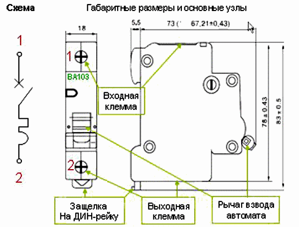
Scheme of a single-pole machine
An automatic machine with one pole is installed in the break of the phase wire and disconnects it from the load in the event of an emergency (fig. below). According to the principle of operation, it is no different from the machines installed on the outlet lines, but its current rating is higher (40 A).
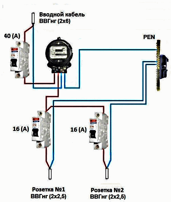
Diagram of an introductory single-pole machine
The red supply phase is connected to it, and then to the meter, after which it is distributed to group machines. The blue neutral wire goes directly to the meter, and from it to the N bus, then it is connected to each line.
The input machine installed in front of the counter must be sealed.
The introductory machine protects the input cable from overheating. If a short circuit occurs on one of the branch lines from it, its automatic machine will work, and the other line will remain operational. Such a connection scheme allows you to quickly find and fix a malfunction in the internal network.
Bipolar
A two-pole is a block with two poles. They are equipped with an integrated lever and have a common interlock between the shutdown mechanisms. This design feature is important, since the PUE prohibit breaking the neutral wire.
It is not allowed to install two single-terminal networks instead of one two-terminal network.
An introductory machine with two poles is used for single-phase input due to the peculiarities of the connection schemes in old houses. A branch is made to the apartment from the riser of the interfloor electrical panel with a single-phase two-wire line. The Zhekovsky electrician can accidentally swap the wires leading to the apartment. In this case, the neutral will be on the introductory single-phase machine, and the phase will be on zero tires.
To ensure a full guarantee of disconnection, it is necessary to de-energize the apartment shield using a two-terminal network. In addition, it is often necessary to change the packet switch in the floor board. Here it is more convenient to immediately replace it with a bipolar introductory machine.
A network with phase, neutral and ground with standard color marking goes to the apartment of the new house. Here, too, the possibility of confusing wires due to the low qualification of an electrician or simply a mistake is not ruled out.
Another reason for installing a two-terminal network is to replace plugs. On the old apartment shields, there are still plugs that are installed in phase and at zero. The wiring diagram remains the same.
PUE prohibit the installation of fuses in zero working wires.
It is more convenient to install a two-terminal network in this situation, since there is no need to redo the circuit.
When connecting electricity to a private house according to the TT scheme, a two-pole is necessary, since in such a system a potential difference may appear between the neutral and ground wires.
On fig. below is a diagram of connecting electricity to an apartment with a single-phase input through a two-pole machine.
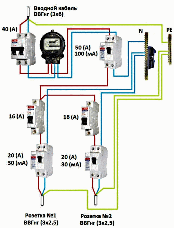
Input scheme with a two-pole machine
The supply phase is supplied to it, and then to the meter and to the RCD fire protective grounding device, after which it is distributed to group machines. The neutral wire goes directly to the meter, from it to the RCD, the N bus, and then connects to the RCD of each line. The zero green ground conductor is connected directly to the PE bus, and from it it goes to the ground contacts of sockets No. 1 and No. 2.
The input circuit breaker protects the input cable from overheating and short circuit. It can also work with a short circuit on a separate line if another machine is faulty there. The ratings of the meter and fire protection RCD are selected higher (50 A). In this case, the devices will also be protected by the introductory machine from overloads.
Three-pole
The device is used for a three-phase network to ensure the simultaneous shutdown of all phases in case of overload or short circuit of the internal network.
A phase is connected to each terminal of the three-pole. On fig. its appearance and diagram are shown below, where for each circuit there are separate thermal and electromagnetic releases, as well as an arc chute.
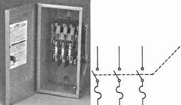
Three-pole machine in the cabinet and its circuit
When connected to a private house, an introductory circuit breaker is installed in front of an electric meter with 63 A protection (Fig. below). After the counter, an RCD is placed for a leakage current of 300 mA. This is due to the large length of the electrical wiring at home, where there is a high leakage background.
After the RCD, the lines are separated from distribution buses (2) and (4) to sockets, lighting, as well as separate groups (6) for supplying voltage to extensions, three-phase loads and other powerful consumers.
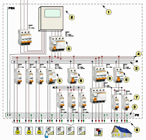
Three-phase network of a private house
Automated Input Calculation
Regardless of whether the machine is introductory or not, it is calculated by summing the currents of the lines outgoing to the loads. For this, the power of all connected consumers is determined. The rating is determined for the simultaneous inclusion of all consumers of electricity. According to this maximum current, the nearest nominal value of the machine is selected from the standard range downwards.
The power of the introductory machine depends on the rated current. With a three-phase power supply, the power is determined by how the loads are connected.
It is also required to determine the number of switching devices. Only one switch is required per input, and then one for each line.
On powerful appliances such as an electric boiler, water heater, oven, it is necessary to install separate machines. The shield must provide a place for installing additional circuit breakers.
Choice of VA
Device selection is based on several parameters:
- Rated current. Exceeding it will lead to the operation of the machine from overload. The selection of the rated current is made according to the cross section of the connected wiring. For it, the permissible maximum current is determined, and then the nominal current for the machine is selected, having previously reduced it by 10-15%, leading to the standard series downward.
- Maximum short circuit current. The automaton is selected according to the PKS, which must be equal to or exceed it. If the maximum short circuit current is 4500 A, a 4.5 kA automatic machine is selected. The switching class is selected for lighting - B (I start > I nom 3-5 times), for powerful loads such as a heating boiler - C (I start > I nom 5-10 times), for a three-phase motor of a large machine or welding machine - D (I start > I nom 10-12 times). Then the protection will be reliable, without false positives.
- Installed power.
- Neutral mode - type of grounding. In most cases, it is a TN system with different options (TN-C, TN-C-S, TN-S),
- The magnitude of the line voltage.
- Current frequency.
- Selectivity. The ratings of the machines are selected according to the distribution of loads in the lines, for example, the automatic input is 40 A, the electric stove is 32 A, other powerful loads are 25 A, lighting is 10 A, sockets are 10 A.
- Power scheme. The machine is selected according to the number of phases: one, - or two-pole for a single-phase network, three, - or four-pole for a three-phase.
- Manufacturer. In order to increase the degree of safety, the machine is selected from well-known manufacturers and specialized stores.
The number of poles for a three-phase network is four. If there are only three-phase loads with a delta connection, a three-pole machine can be used.
The switch at the input must turn off the phases and the working zero, since in the event of a leakage in one of the phases to zero, there is a possibility of electric shock.
A three-pole machine can be used for a single-phase network: phase and zero are connected to two terminals, and the third will remain free.
The choice of an introductory machine depending on the type of grounding:
- TN-S system: the supply neutral protective and working wires are separated from the substation to the consumer (fig. a below). To simultaneously turn off phases and zero, two-pole or four-pole input automata are used (depending on the number of phases at the input). If they are with one or three poles, the neutral is carried out separately from the machines.
- TN-C system: the supply neutral protective and working wires are combined and pass to the consumer through a common conductor (Fig. b). The machine is installed single-pole or three-pole on the phase conductors, and zero is entered through the counter on the N bus.
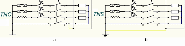
Schemes of common types of grounding
Installation
The input automat is installed in the shield from above, on the left side. It is convenient to mount the outlet lines from top to bottom. With a small number of loads, it can be single-pole and connected via a phase wire. In this case, a complete break in the supply circuit does not occur.
Mounting is usually done on a DIN rail, when the power is turned off.
Video about the electrical panel
The answer to the question of how to switch the input electrical panel can be obtained from the video below.
As practice shows, connecting an introductory machine is not a difficult job. It is important to correctly calculate it in terms of power, think over the wiring diagram and install it taking into account the features given in the article.