
Do-it-yourself iron repair is a classic of the household genre, but now, unfortunately, the jets of surrealism are becoming stronger in it. A newbie master, in order to disassemble a modern iron, needs to have the skills of solving Chinese puzzles: everywhere hidden latches, clever spike joints, shaped fasteners. Carry to the workshop? The price of repairs may turn out to be such that it is easier to buy a new iron. Let's try to fix our own, without professional training and without having a special tool.
Distracted thinking
Manufacturers justify the transformation of the iron into a kind of combination lock with the requirements of safety, design and ergonomics. But, sorry, from the visible fasteners on the irons, as there were 1-2 screws in the back, it remained. Moreover, the details of the bodies of old irons were made of their brittle bakelite and polystyrene, and the current plastics compete with metals in strength.
In fact, we, alas, live in an age of non-eternal things. One of the fundamental attitudes of the consumer society is inexorable: a product of mass demand must work flawlessly (the reputation of the manufacturer, and of course) no more than 2-2.5 warranty periods, and then quickly and irreversibly come into complete disrepair. At leading manufacturers of consumer goods, up to half or more of the design personnel are involved in ensuring that, God forbid, the product does not turn out to be too durable.
How the work of the industry for the trash can affects the environment, and the involvement of really high-class specialists in actually harmful activities on the mass consciousness, is another question, but the iron almost does not lend itself to such attempts: it is too simple, but inside it is too hot and humid. Therefore, damage to the iron at the design stage is mainly reduced to making it difficult to disassemble it outside the service center. Nevertheless, it is still possible to fix the iron at home with improvised means if you know where and what secrets can be hidden in it and how to open them without risking permanently ruining the iron.
Tool
To successfully repair your iron, let's prepare some homemade tool first; it will not take much time and will not require significant expenses:
- 2-4 squeezers for caps;
- wringer for hidden latches;
- a cheap LED flashlight (namely LED) and a magnifying glass;
- a strip of suede, a nail file, alcohol;
- or, instead of item 4 - pencil eraser, ink eraser, a piece of clean cloth, alcohol.
Note: on the appointment of tools according to PP. 4 and 5 see below.
Squeezers
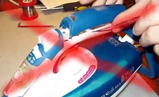
The squeezer for lids is made from the top, most durable layer of bamboo, the size and thickness of an ice cream stick; one end is cut into a wedge. The lids on the body of the irons are often put on latches without fixing. In the service center, such a cover is squeezed with special pliers and removed. To remove it in an artisanal way, the cover must be pry off: the teeth of the latches are chamfered on both sides without fixation and come out of the grooves intact. But to open the lids on tight latches with a table knife or a wide screwdriver, as in Fig. on the right, don't: the steel will leave marks on the plastic. The bending strength of the surface layer of bamboo is higher than that of plastics, and the shear strength is lower. Therefore, the bamboo squeezer will remove the properly pushed lid, but, perhaps, it will wrinkle from the surface without damaging the plastic. If the lid is not hooked up incorrectly and does not lend itself, the bamboo squeezer will break without damaging the iron. They act with bamboo squeezers in pairs, prying the part from 2 sides.
A good slender squeegee for locking latches comes from a wedge-cut plastic coffee stirrer that vending machines dispense. The squeezer from the mixer goes into any slot and gently removes the mustache of the latches with fixation, without scratching or breaking either them or the body parts.
Flashlight and magnifier
Cheap mini LED flashlights produce very hard light with harsh shadows. In this case, this is an advantage: such light penetrates deeply into thin slits, and under a magnifying glass you can see what the detail is holding there. To do this, first, they pry off the lid, which it is not clear how to remove, with bamboo squeezers, highlight and examine what it holds there.
How to handle latches
The best thing, of course, is to find a disassembly diagram for the iron of this model, but try it! And do not look for typical schemes for the location of secret constipations: they may be different for the same model of the same manufacturer. Have you read in the instructions: "The manufacturer reserves the right to make changes to the design that do not affect the performance of the product"? That is, when disassembling the iron, you will most likely have to look for hidden connections yourself.
I must say that Western firms are gradually moving away from the principle: “Do you want to fix it yourself? Well, break it and buy a new one! " But Asians cling to it stubbornly. For example, if your iron is Chinese, then the nose fixing screw (see below) will most likely be not under the filler cap, but ... under the water and steam buttons!
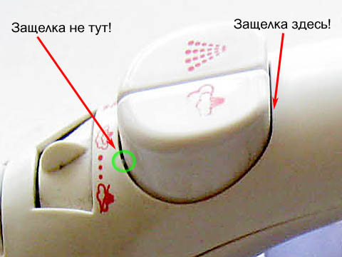
Let's highlight and see. See the green circled in the pic? So, this is not a latch, but a sliding spike in the groove. Latches on the other side of the buttons. To remove the buttons and disassemble the iron, you need:
- Push the button forward.
- Insert a squeegee from the mixer behind it.
- Release the latch.
- Without removing the squeezer, lift the button up to the stop. You should hear a faint click of the latch tooth coming out of the slot.
- While holding the button so that it does not fall, remove the wringer.
- While continuing to hold the button, push it forward at an angle so that the sliding pin is twisted out of the slot.
- Do the same with the other button.
Shaped fasteners
The screws in the irons of Western manufacturers are most often either conventional with a Phillips head or a hexagon. It makes no sense to buy for the latter a special screwdriver with a set of bits for a one-time repair: a screw with a hexagonal slot is simply unscrewed with a flat screwdriver with a thin tip of a suitable width. It can also be used to loosen the trefoil slotted screws, which the Chinese are very fond of (on the right in the figure), but without strong pressure: this creates a significant lateral force and the screw in the thread can simply jam. If the screw sits tight, it is torn off with a series of small jerks, moving the screwdriver to other pairs of slots.
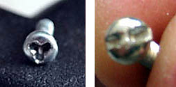
The most difficult thing will be to unscrew the TORXX slotted screw (on the right in the figure): scissors or tweezers will take it only if the screw is loose in the thread. It is most convenient to unscrew the TORXX screws without a special key using small pliers; it is possible with side cutters, but then dents will remain on the jumper of the slot. There will be nothing from them to the screw, but an experienced craftsman, suddenly this iron gets to him, will throw it over for repairs for the previous unqualified access.
How the steam iron works
But where to find all these secret cogs? To do this, you first need to get acquainted with the device of a modern iron with a steam generator (steamer). Its general scheme is shown in Fig.:
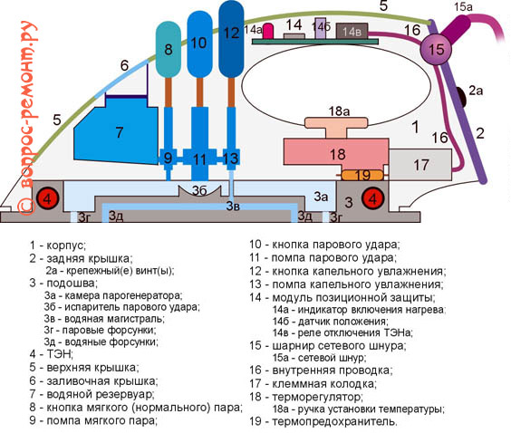
The shock steaming system (superheated steam) is installed only in certain models, because it is effective only when the thermostat is close to the maximum (three points). In good irons with shock steam, the shock pump is blocked if the regulator is set at 1-2 points. What is always written in the instructions, how what, pray tell, a normal housewife reads the instructions for the iron? That is, if there is no steam boost, then, perhaps, to eliminate the "malfunction" you just need to turn the temperature regulator.
The positional protection module turns off the heating element if the position of the soleplate of the iron differs from the horizontal position: it was placed upright, dropped, etc. This is perhaps the only electronic innovation in irons. In high-quality irons, positional protection is the second most frequent source of breakdowns (after scale in the steamer, see at the end), but at home it is most often quite maintainable.
How the Chinese soar
If you look at the sole of not even cheap Chinese irons, it turns out that many of the drip humidification nozzles are fake, fake. In fact, when fully heated, a steam boost is obtained if you press the steam button; in the same position of the thermostat, soft steam comes from the button with droplets, and for drip humidification, in this case, you need to press both buttons at once.
Wiring diagram
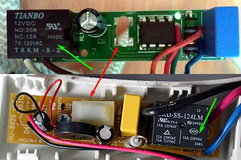
The wiring diagram of the iron is shown on the next page. rice.:
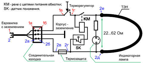
The KM relay and the SK position transmitter constitute the position protection. On its own board, there may be a power indicator, which in this case is LED, and not on the neon. Positional protection can be turned off without prejudice to the consumer qualities of the iron, but if the indicator is LED, then when the “positioning” is completely turned off, it will stop working. This is inconvenient, so the faulty positional protection must be partially disconnected (see below).
The numbers with indices show the sequence of dialing the "hot" and "cold" circuits with a multimeter: one probe with a crocodile clip is connected to the plug of the power plug, and the others go along the points. Both dials should converge on the contacts of the KM relay. The fact is that the KM contacts are normally open: when the iron is connected to the network and the contacts of the KM thermostat are closed, it pulls, its contacts are closed and current flows through them to the heating element. So it is necessary that any malfunction of the positional protection itself turns off the heating element (the principle of redundant safety), but this circumstance can be misleading for an inexperienced master.
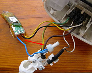
Note: when dialing, it may turn out that the non-contact is in the connecting cap, see fig. on right. The only way out is to bite off it and reseal the wires in a new one.
Thermal protection
A thermal fuse (thermal) is triggered if the temperature of the sole of the iron exceeds 240 degrees or the current through the heating element is a certain set value. That is, the thermal fuse, instead of the unusable one, must also be selected by current, depending on the power of the iron:
- 2200 W - 25 A.
- 1500 W - 16 A.
- 1000 W - 10 A.
- 600 W - 6.3 A.
Excessive thermal current is needed, because 220 V is the effective (effective) value of the mains voltage; the amplitude is 220 V x 1.4 = 308 V. The half-cycle duration of the 50 Hz frequency is 10 ms, and the thermal response time is 4-5 ms. Suddenly, the mains voltage will jump to the maximum permissible value of 245 V, the thermal fuse for the operating current of the heating element can burn out in a perfectly working iron.
Thermal fuses are disposable (pos. 1 in the figure), recoverable, pos. 2, and self-healing, pos. 3. The first ones burn out and must be installed in a dielectric heat-resistant sleeve (usually made of fiberglass), otherwise a breakdown of the mains voltage to the sole is very likely. In a recoverable thermal fuse, the prestressed bimetallic plate "flips" and opens the contacts. To restore it, you need to squeeze something sharp through the window in the contact until it clicks back. The self-healing thermal protection will return to its original state if the iron is unplugged and allowed to cool completely. Self-healing thermals are structurally combined with a thermostat (see below) and are always supplemented with a current fuse.
Thermostat
The soleplate temperature regulator is the most important unit of the iron and one of the most prone to breakage; it is a mechanical trigger device driven by a bimetallic plate. There are no "magnets, like in the refrigerator regulator" in the iron's thermostat. As in the thermostat of the refrigerator, there is also a mechanical trigger, only of a different design. Its principle of operation is simple:
- A part with a moving contact is pressed against a fixed changeover spring. The contacts are closed, the heating element is heating. The compression ratio of the spring is adjusted with the temperature setting knob.
- On the other hand, the movable contact is connected by a dielectric pusher rod to a bimetallic plate.
- The bimetallic plate, bending from heating, presses through the rod on the movable contact until it overpowers the spring.
- The spring throws over and opens the contacts.
- The heating element turns off, the sole of the iron with a bimetallic plate cools down.
- The bimetallic plate is straightened. When its pressure is sufficiently weakened, the spring is thrown back and returns the regulator to its original state.
The heating element heats up again, the cycle repeats. In old irons and parts of new ones, the thermostat is assembled according to the scheme with a free rocker (item 1 in the figure):
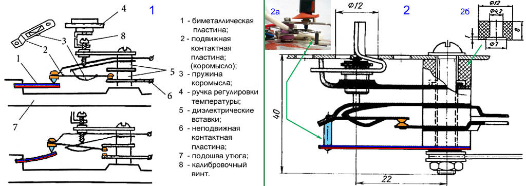
Its disadvantages are 2 pairs of contacts prone to sticking, and a large hysteresis, i.e. the difference between the response and return temperatures of the regulator. Therefore, regulators with a free rocker always have an adjusting screw under the handle, which is twisted if the iron heats up too much (twist 1-2 turns) or weakly (twist the same). The temperature adjustment knob must be removed to access the calibration screw. It sits on the axis under friction, but is held in the body by paws with stops, see fig. on right. To remove the handle, it must be turned at least until it stops (beyond the first point) and pulled up.
Most modern irons are supplied with a unified double spring-loaded thermostat, pos. 2: it responds very clearly and almost never requires readjustment during operation. Its weak points, firstly, as in the previous. case, contacts, see below. Secondly, the ceramic rod (marked in blue), which sometimes cracks. The stem length is 8 mm, and a new one can be made from an MLT-0.5 W resistor, pos. 2a. The resistor leads are bitten to a length of 1.5-2 mm, the paint is washed off with dichloroethane or a surfactant remover, the conductive layer is cleaned with sandpaper. If the resistance of the resistor is more than 620-680 kOhm, someone puts it instead of the rod as it is, the paint burns without smoke and stench. However, then the sole of the iron can be unpleasantly "pinched" by electricity. And what is much worse, the resistance of a resistor with an unprotected conductive layer can decrease several times, and the leakage current through it can rise to a dangerous value.
Note 3: sometimes washers-inserts crack in thermostats. A new one can be turned out of fluoroplastic instead; for drawing see pos. 2b.
How to clean contacts
It is not necessary to clean the burnt contacts of the iron temperature regulator with sandpaper, as advised in many sources: they work under high current and, after cleaning with sandpaper, they quickly burn again. In the regulators of modern irons, the contacts are thin-walled stamped, and in this case they burn out to holes. To clean the contacts, you need to wrap the nail file along the suede moistened with alcohol, stick it between the contacts and rub until the suede stops getting very dirty with carbon. An alternative is to cut a thin wedge out of an ink eraser and clean the contacts with it. Then - with the same wedge from a pencil eraser. Finally, wrap the nail file with a rag moistened with alcohol instead of suede and remove the sticky eraser particles from the contacts.
Note: due to the thermostat, such a situation is also possible - the iron heats up at maximum regardless of the position of the temperature setting knob; adjusting the calibration screw does not help. This means that the contacts of the regulator are welded and it needs to be changed.
How to get there?
All this is good, but our iron has not been disassembled yet. In general, the disassembly of the iron is done next. way:
- Remove the temperature setting knob.
- Remove the back cover (possibly together with the top one).
- Remove the terminal block.
- Remove the top cover.
- Remove the case.
- Remove the thermostat cover (if any).
After that, all the units of the iron become available for inspection and repair. Of course, each stage has its own subtleties and peculiarities. We will consider some further not examples of models of individual manufacturers, but for now we will focus on general "troubles".
Back cover
This is the only part that is secured with an externally visible screw (s). The latter may be 2 at the bottom. In this case, 2 options are possible: the back cover is at one with the top and separately. In the first case, the iron handle will be straight, and both covers are immediately pulled back, pushing the upper one with your fingers: it sits with horizontal spikes in the longitudinal grooves.
If the covers are separate and the back cover is on one or 2 screws, then again 2 cases are possible: the back cover is flush with the body and overlay. In the first case, the lid is pulled by the bottom towards itself - at the top it is fixed with spikes in the grooves, which will turn out and the lid will come out. The second case concerns almost exclusively covers with one screw in the middle. If the cover does not come out after unscrewing the screw and does not stretch beyond the bottom, then the spikes with the grooves are double, at the top and bottom. Then the cover needs to be pushed up so that the lower spikes are released, and then pull the bottom so that the upper ones are turned out of the grooves.
Block
After removing the back cover, the terminal block will be visible, this is already a hotbed of malfunctions. In some irons (not necessarily cheap), the terminal block is ordinary screw (item 1 in the figure), it can melt, then you need to change it to propylene. Polyethylene and PVC will not stand in the iron!
Blocks with captive terminals (pos. 2) are most reliable, but for further disassembly of the iron, the terminals must be removed. To do this, their lugs are squeezed out through the holes in the contacts with an awl or a thin screwdriver.
To remove the one-piece cutter block (pos. 3), you need to unscrew the 2 screws of the power cord clamp and 2 screws holding the block itself. If the network wires do not ring on the acc. sockets of the block (green arrows at pos. 4), the block must be changed or plug-in terminals must be put on the wires, because the wires in the cut-in block cannot be repaired.
Top cover
The curved top cover is secured by tight latches without locking. At home, it is removed with a pair of wringers (see above), starting, as a rule, from the rear end. Doesn't work - you need to try from the front.
Positional protection
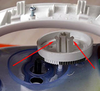
Most irons have a positional protection module under the top cover. The most vulnerable in it is the position sensor. As a rule, this is a plastic box (red arrows in the figure) only with a pair of leads. The position sensor is either closed with a tight-fitting lid, or is filled with a compound on top, which can be picked out.
A malfunction of the position sensor is typical: the iron does not turn on, and if you shake it, it can turn on for a while and turn off spontaneously again. When disassembling the sensor, it is found that there is a pair of contacts and a metal roller covered with something viscous and dirty. Initially, the sensor was filled with a clean and transparent silicone grease, but the coil current of the powerful relay is sufficient to make the contacts spark. The filling becomes dirty with carbon deposits, the roller does not close the contacts well and does not move as it should.
The unusable silicone is removed with table vinegar, but you cannot leave the roller dry: when ironing, the relay will “clap” all the time, the iron will heat up unpredictably, and the sensor will soon fail completely. Instead of silicone, the sensor must be filled with any liquid machine oil; By the way, it is more resistant to pollution and better dampens sparks than silicone. The sensor is washed with alcohol, a needle from a medical syringe is put on the nozzle of the oiler and the sensor is filled carefully so that the oil does not flow onto the walls. After filling, the lid is glued back with "Titanium" or other superglue, but if the walls are oiled, then the glue will not hold.
Note: in irons Brown and some. other signals from the position sensor are processed by the microcircuit (upper position in the figure). In this case, it is permissible to leave the position sensor roller dry.
Another possible malfunction is burnt contacts or a blown relay coil, then the iron will not turn on at all. To check the module, you need to remove it from the iron and apply its operating voltage, DC or AC, to the relay coil, which is indicated on the relay case (green arrows). A click should be heard, and the tester should show the contacts are closed. No - the relay needs to be changed.
Note: if you are not sure that the winding voltage is indicated on the relay, you need to measure its resistance. Suddenly, the winding current at the specified voltage turns out to be more than 80-100 mA, it cannot be applied to the winding. You need to check the relay from a regulated power supply. Typically, the operating voltage of the winding does not exceed 24 V.
It is quite possible to do without positional protection. To partially turn it off (for the heating element indicator to work), you need to evaporate the white wire and connect it to the brown one, or evaporate the red one and connect it to the blue one. At the same time, the relay can click and rattle, so it is better to evaporate it too.
Frame
After removing the back cover and the terminal block, the spikes holding the body in the grooves (lower position in the figure on the right) or screws will appear, but do not rush: the body holds another screw or two in the area of the iron spout. It has already been said how the Chinese hide them, but in other irons they are on the spout under the filler cap. It remains in place after removing the top cover. To remove the neck cover, you need to lift the filler flap and remove the cover with it with squeezers, then the nose screws will be visible (upper pos.)
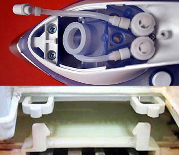
The iron body is removed together with the pumps, and their malfunctions become visible, from which either there is no steam, or water flows into the body, the iron cracks, sparks, beats with an electric current: cracked pipes, nozzles and valves (nipples) clogged with salt deposits. It is not necessary to glue the tubes, in the iron there is any glue that is a dead poultice. First, you need to descale the hydraulic system. For plastic, this is done mechanically, with a cotton swab soaked in alcohol. The nipples are washed with a citric acid solution (1 tsp per glass of water). Acetic acid solution (vinegar) emits chemically aggressive vapors that corrode metal. Then the fragments of the cracked tubes are put together, pieces of a heat-shrinkable tube (HERE, heat-shrink) are put on them and heated with a household hairdryer.
What's wrong with anyone
Tefal
The repair of the Tefal iron is distinguished by its originality. First, the body can be removed together with the top cover. Second, the nose screw is hidden under the cover of the water dispenser (left and center in the figure); it is visible through translucent plastic. Third, to get to the pumps, you need to remove the top cover with the case removed. Its screw is hidden under the buttons (on the right in the figure), and it must be unscrewed in order to remove the cover.
Finally, Tefal is the leader in cordless irons. They are of several types: with contacts on the site, with a thermal accumulating sole, with a rejected (shoot back) cord. The first two are unsuitable for amateur repair, and the last, seemingly faulty, may turn out to be quite working.
The cord from the iron throws a pusher, acting from a separate trigger mechanism with its own bimetallic plate. That is, if, for example, you ironed the cuffs and want to warm up the iron by inserting the cord, but it does not fit, then the iron has not cooled down enough. You need to let it cool down, insert the cord, turn the regulator to a higher temperature and wait until the cord bounces off. It is inconvenient, of course, that's why irons with a detachable cord are not in great demand.
Phillips
A feature of Philips irons is a double body. For example, the popular Azur is first dealt with in the usual sequence, pos. And in the figure, but the rear cover is fastened with 2 screws from the bottom. Under the decorative case with pumps, there is an inner one with protection (pos. B), and already under it is a massive sole (in fact, the third case) with a thermostat and a thermal, pos. V.
Bosch
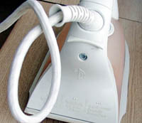
The design of Bosch irons can be considered typical, and Bosch disassembly is even easier than others: the back cover is on one screw and without tricky fasteners. To remove it, you need to unscrew the screw and pull back on the power cord inlet hose (see the figure on the right), the cover will open together with the hinge, after which further disassembly has no special features.
Brown
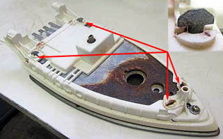
A congenital defect of inexpensive Brown irons is a thin-walled steam generator tank made of galvanized steel and fastening the thermostat casing with bendable paws from it. Both rust perfectly, see fig. on the right, after which repairing the iron becomes meaningless.
How to make steam
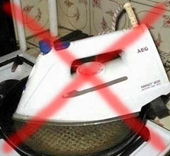
The same congenital defect of all steam irons without exception is scale. It is difficult to remove it from the non-separable reservoir of the steam generator, and in no case should the iron be boiled in a pan with vinegar for this, as in Fig. Vapors of acetic acid will brittle plastics, corrode nickel on the sole to a roughness, and if it is coated with Teflon, it will begin to flake off. First, the iron for cleaning must be disassembled to the sole, see eg. video how to clean Philips 3240:
Video: example of disassembling and cleaning the Philips iron 3240
Secondly, as already mentioned, it is better to use not vinegar, but a solution of citric acid. Thirdly, before cleaning, the contacts of the heating element together in ceramic bushings must be tightly wrapped with good soft electrical tape in 3-4 layers or, better, with heat-shrinkable tape. Fourthly, if the nozzles are clogged with scale, also pierce with a toothpick before cleaning. And fifthly, after cleaning, rinse the sole hydraulic system abundantly with clean water from top to bottom, pouring it into the steam generator tank. Then you can rest assured: the iron will serve as well after cleaning as before.