
A board with a built-in system for receiving pulse information signals is called a relay. We propose to consider what a pulse time relay is - its description and purpose, how to make it yourself, the principle of operation, as well as detailed instructions and a diagram of connection to the power supply system.
The principle of operation of the relay
Impulse relays have a strong advantage over conventional relays because they do not require a constant supply of power or voltage in order to operate as needed. Due to their energy, which is quite efficient in nature, the inclusion trimmer is used in a huge variety of electronic devices.
All relays contain a sensor unit and an electric coil, which is powered by an AC or DC source. When the applied current or voltage level exceeds a threshold value, the coil activates a mechanism that acts to close open contacts or open closed ones. When power is applied to the coil, it generates a magnetic force that drives the switch mechanism. Magnetic force is essentially a transferring action from one circuit to another. The first circuit is called the control circuit, and the second is the load circuit. Due to the fact that the impulses are produced almost exclusively with the help of electromagnetic fields, this device is silent.
The second circuit is also responsible for the state of the relay memory. The fact is that any modular low-voltage relay is equipped with a memory mechanism. Those. the device saves the latest data about connections, network status and its operation.
In principle, most of us have a question, why do we need a relay, if you can monitor the lighting using a regular pass-through switch? The fact is that even the simplest relay has a much wider range of action, it can be used to control lighting from three or more places, while not making any special efforts to connect it. Consider the types of relays.
relay type
This electronic device is of several types:
The vast majority of the relay works with various neon lights, LED lamps and other small and relatively unloaded lighting fixtures. But, unfortunately, the simplest impulse group or two-state relay, for example, models from legrand, acti, Colan, dc, electric Schneider, gerin, general, esmi etimat, fotek, fujitsu, hager, moeller, iek, itl, merlin, multi , pulsar, sassin, Siemens, tlc, zamel, finder, their cost is about 1000 rubles (although the price of domestic ishm is slightly lower - from 700 rubles). Therefore, we will tell you how to assemble such a device at home.
Video: Pulse Relay Wiring Diagram - Part 2
How to make an impulse relay yourself
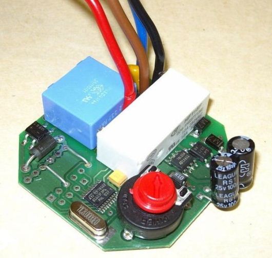
We propose to take a solid-state polarized relay with a timer as a basis for work. As an example, this could be a 12v instant response device. The programmable nature of this switch means it can be used in a variety of ways. You can use the Legrand or Schneider scheme, depending on the needs of the machine.
A double pole latching relay needs 2 switches to operate, while a homemade single pole relay needs a polarity reversal to operate. You need to buy not only an impulse relay, but also a box for it (visit any electrical shop in your city - Kyiv, Moscow, Perm, St. Petersburg, Kharkov, Yekaterinburg, Dnepropetrovsk). Our device has the following characteristics:
- 0.03mA and 12v (this is a great circuit for solar panels)
- Output current - 7 a;
- Four switches.
In latched mode, this will cause an instantaneous pulse whenever a signal is received. In this case, the trigger input contacts are fixed in the closed on position, as soon as the next impulse occurs, they turn off, and the contact on the second relay output is fixed in the same way.
Video: how to connect an impulse relay yourself (diagram) - Part 1
There are two timer ranges, zero to 1 second, or 1 to 100 seconds. You can set up absolutely any mode, but for industrial buildings it is much more profitable to connect devices or systems with a long period of time, but for domestic use - with a minimum.
The device comes with 2 sets of wires, one for output (heavy gauge wire, 7 amps) and one for input control (lighter wire, melted into 3 amps). Here is the basic information on how to connect a small-sized impulse relay with abb (abb) type wires:
- Cable 1 (INPUT: 3-pin connector):
- Red: +12 Power for re-operation operation of internal circuits (3 A fuse)
- Black: 12v ground
Green: Trigger input, provides input pulse to control latch operation. You can connect this line on one side with a spring pushbutton switch, and on the other side with a contact to + or - a power source (it all depends on the purpose, you can also use a car battery, as Volga, Gaz, VAZ and others using relays for fog corners, as well as general light in cars, alarms, etc.).
Cable 2 (OUTPUT: 2-pin connector):
- Brown: connect to +12 volts or -12V depending on the polarity of the yellow wire;
- Yellow: This is load power control, you need to connect it with brown wire and ground
In principle, this is a standard design, the most difficult thing in it is to choose a counting-wire and latching relay.
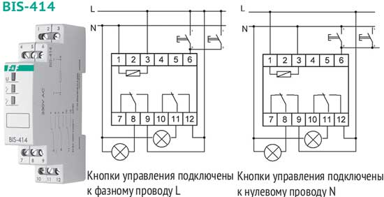
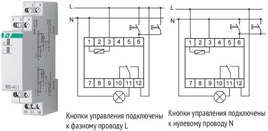
Operation is carried out when the switching mechanism is pressed for the first time. The front contacts turn on as soon as the rear contacts are closed. When you finish reading our relay wiring course, don't forget to watch the detailed video.