
No electrician - professional or beginner - can do without a measuring device - a multimeter. With it, you can measure the voltage in the network, check the integrity of the wires and other parameters and characteristics of electrical circuits and their elements. In this article we will talk about how to use a multimeter.
A multimeter is a versatile measuring instrument that can measure several electrical quantities. The list of measurements depends on the model and may vary significantly. The basic set of functions is to determine the strength of the current (DC and AC), voltage, resistance. Such devices are relatively inexpensive.
In general, you can find models that can determine the capacitance of capacitors, current frequency, temperature, can ring diodes, determining the voltage drop across the P-N junction, generate signals of a certain frequency, etc. The more possible features, the higher the price. The price also depends on the degree of “hype” of the brand and on the build quality.
There are also two types of multimeters: with a pointer and a digital indicator. Models with digital display are more popular - information is easier to read.
As you can see, there can be so many functions that the question arises: “How to use a multimeter?” This is what will be discussed further.
External device
Multimeters are also called testers or multi-testers, as they allow you to measure several different parameters and characteristics. But when they say "tester" they usually mean a device with a dial indicator. They use it infrequently, since it is necessary to calculate the values on a scale, taking into account the set threshold of the measuring scale.
When using a digital device with a liquid crystal display, these problems are not present - the result is ready. That is why, basically, everyone uses multimeters. Before you learn how to use a multimeter, let's understand its structure. This will allow you to quickly master the skills of working with this measuring device.
General structure and purpose of connectors
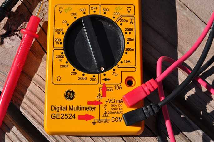
A digital multimeter is a small instrument, less than half the size of a notebook sheet. It weighs 200-300 grams. At the top is a display that shows the measurement readings. In the central part of the case there is a switch with which the nature of measurements and their limits are set. In the lower part of the case there are connectors (sockets) for connecting probes. They can be located at the bottom right or along the bottom edge of the case. Also included with the tester are two measuring probes - black and red.
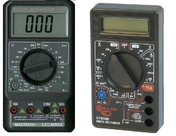
Most often there are three connectors. The lower one is usually signed "COM" - common. The black probe is always connected here. The other two are for connecting the red probe. The top socket is used only in one case: when measuring DC current, the value of which is more than 200 mA. All other measurements with a multimeter are carried out when the second probe is in the middle position.
There are models in which there are four measuring sockets (in the photo on the left). In this case, there are separate sockets for measuring current up to 200 mA, separately for current from 200 mA to 10 A (the numbers may vary depending on the model, but the meaning remains the same). For resistance and voltage has its own socket. All nests are signed, it is not very difficult to understand.
Measurement modes and limits
In order to understand how to use a multimeter, you need to carefully consider the mode switch, consider where and what designations, modes.
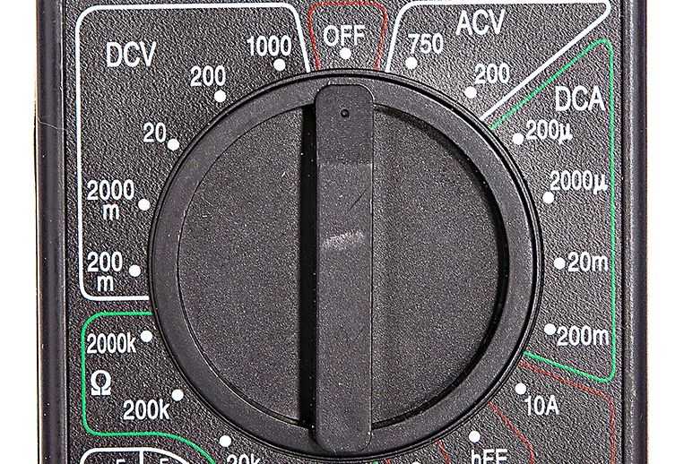
The number and position of the modes depends on the model, but in most of them there are:
- OFF position - turning off the device.
- ACV - for measuring alternating voltage. In some models, there may be a letter V and a wave under it.
- DCA - for direct current up to 200 mA. It can be denoted by the Latin A and an even line under it.
- 10 A - for direct current from 200 mA to 10 A (in some models, these figures may be different).
- HFE - to check the gain of transistors. This mode is not available in all models.
- The image of a diode or a megaphone is a socket for testing wires and checking diodes.
- Ω - resistance measurement.
- DCV - constant voltage. There may be a letter V with an even line below.
These are all major modes. As you can see, most of them have several provisions. These provisions define the upper limit of measurement.
How to measure electrical parameters
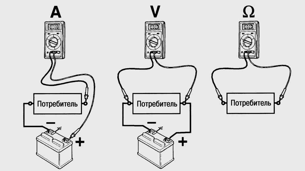
Before we start talking about how to use a multimeter, you need to remember that when measuring current, the multimeter is connected in series - into a circuit break, and when measuring voltage - in parallel with respect to a section or circuit element.
We measure voltage
Move the switch to the voltage measurement position. There are two positions: for direct and alternating voltage. We select according to the parameters of the circuit or device.
Next, you need to select the measurement range. To do this, you need to at least approximately (or better, exactly) know what readings to expect. For example, when measuring the voltage in the network, you know that there will be 220 V or there are inscriptions on batteries or accumulators, on devices there are nameplates indicating the parameters of the circuit. In any case, we set the limit - the nearest larger one. This will provide greater accuracy.
If we don’t know exactly what voltage it can be, we set it approximately - after the first readings it will be possible to change. If we have no idea about the magnitude of the voltage at all, we set the largest limit, further approaching the desired position. Such an algorithm will not allow you to burn the device, which can happen if you set the limit too low.
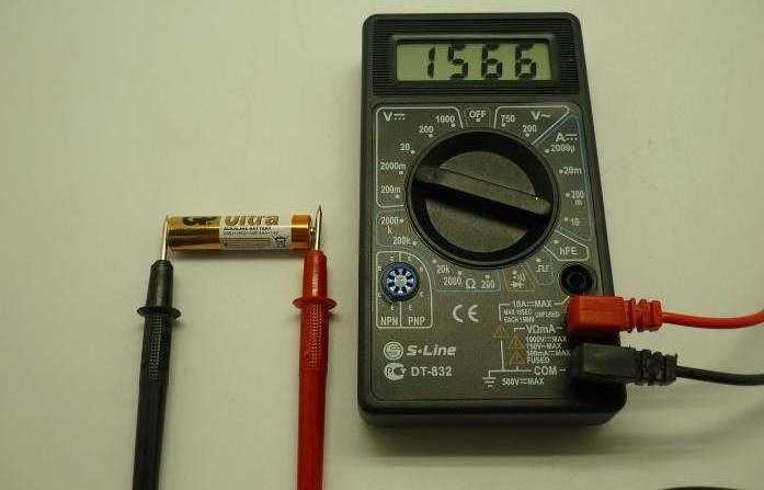
Having decided on the limits of change, we connect the probes:
- black to the common socket "COM", and the second probe - to the minus of the battery or accumulator;
- red to the socket with the inscription VΩmA, and the probe from it to the plus of the battery.
The display shows numbers. This is the voltage in the measured area. In this case, on a battery / accumulator.
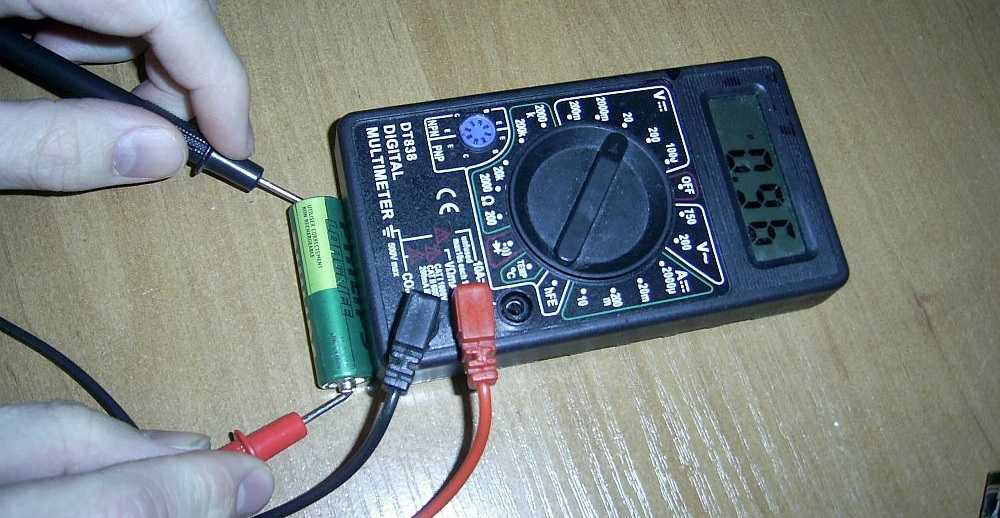
If you mix up the probes in places and connect the red to the plus, and the black to the minus, nothing bad will happen. A minus sign will simply appear in front of the readings.
How to use a multimeter to measure current
Most often, there are two switch positions for measuring current strength - constant and variable. But not in all models. There are devices (M-830, DT-830) that can only measure direct current.
To measure DC current with a multimeter, the procedure is standard:
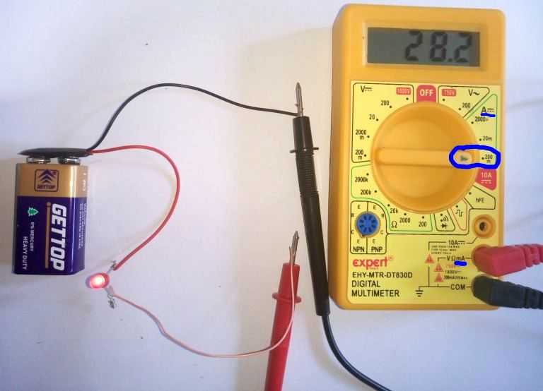
One remark: the assembly of the measuring circuit when measuring the current must be carried out with the voltage removed. At significant currents (above 200 mA), work without removing the voltage is unsafe. Apply power only after the multimeter is connected.
Resistance measurement mode
The position of the multimeter probes for measuring resistance is standard: red in the “COM” jack, black in VΩmA. The free ends of the probes touch the leads of the measured object.
There are nuances with the choice of the measurement limit. If you know what readings should be (check resistors, for example), set the measurement limit to the nearest larger one. If the resistance value is unknown, set the switch to the maximum scale. After measurement, it can be changed to a more suitable one.
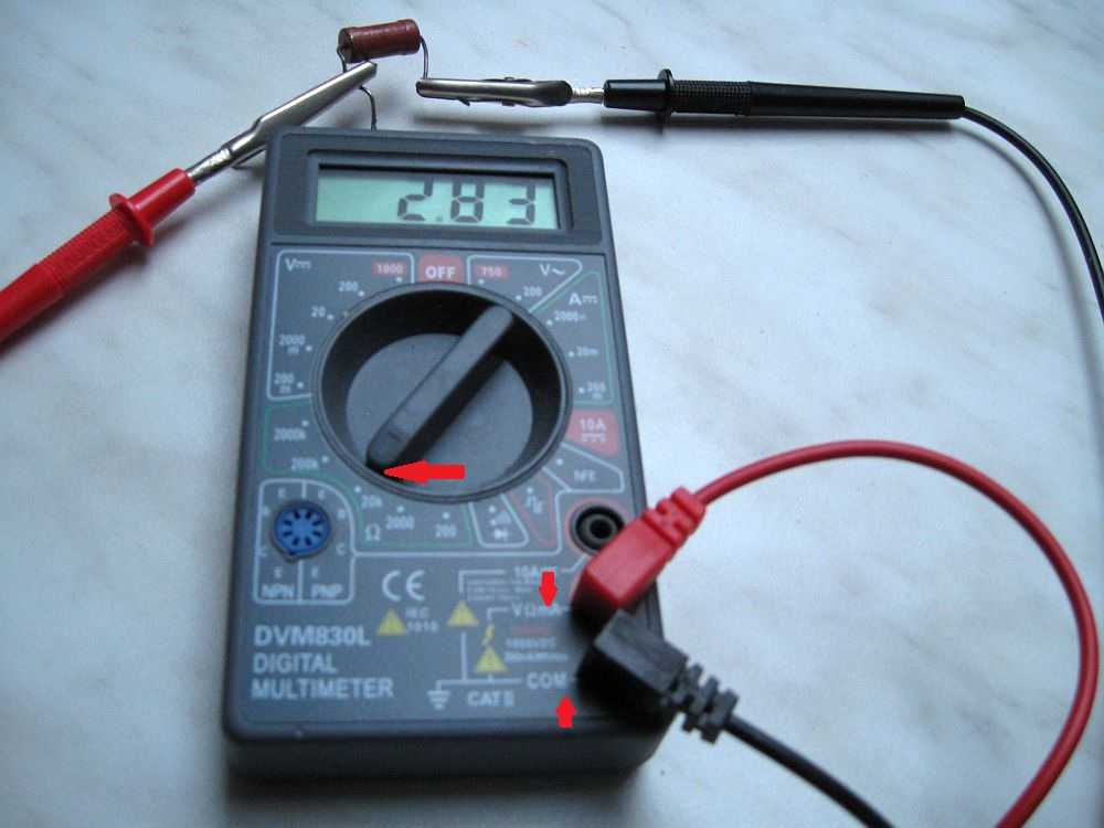
If, when measuring resistance with a multimeter, the number “1” appears on the screen, this means that the measurement limit has been exceeded, you must change it to a larger one.
In this chapter, we will consider how to use a multimeter to check the integrity of the wires or, as they say, for continuity. When is this operation needed? Very often. For example, when something does not work and it is necessary to determine whether the cord is to blame. This is the first step in the repair of any household appliances - checking the integrity of the power cord. And the test is carried out precisely with the help of a multimeter (tester) in the dialing mode.
The second most common case is when, when connecting the cable, they forgot to sign which wire they connected where. In this case, not one end of the probe is held on one wire, but the conductors are sorted out at the other end until a characteristic sound is heard.
Now directly about the procedure itself. First, we put the switch in dialing mode. In this mode, the device emits a squeak if the circuit resistance is less than 50 ohms. If you connected the device to both ends of the conductor and heard a squeak - the wire is intact, if there is no squeak - there is a break somewhere.
Usually, the dialing mode on multimeters is depicted graphically: a pictogram is applied in the form of a horn with outgoing sound waves. We put the switch in this position, set the probes to the standard position - red in the "COM" jack, black - in VΩmA. With the free ends of the probes, touch the ends of the wire under test. When the cable rings, this procedure is repeated with each core.