
Instruments for measuring alternating current can be different.
To measure the power frequency current (50 - 100 Hz), direct assessment devices are mainly used based on electromagnetic and electrodynamic systems, as well as thermoelectric systems.
In low-power high-frequency circuits, the current is measured by rectifier, thermoelectric, electronic digital and analog voltmeters on a resistor with a known resistance. The ammeter should have minimum input resistance, inductances and capacitances.
Devices of the electromagnetic system. The principle of operation of these devices is based on the phenomenon of retraction of a steel plate connected to an arrow by the magnetic field of the coil. The deviation of the moving part of the measuring mechanism depends on the square of the measured current and can be used to measure both direct and alternating current with a frequency not exceeding 5 kHz. By selecting the shape of the core, it is possible to obtain an almost uniform scale. Ammeters of the magnetoelectric system are produced as panel instruments of accuracy classes 0.5, 1.0, 2.5 at frequencies up to 1500 Hz, and 0.5, 1.0 - up to 2400 Hz. To expand the limits of current measurement with an electromagnetic ammeter, not shunts are used, but sectional coils or transformers. Advantages - simplicity of design, low cost and reliability. Disadvantages - low accuracy and sensitivity. Electromagnetic ammeters are used for direct measurement of currents up to 200 A, the coil of the measuring mechanism is connected in series to the circuit of the measured current. The measurement limit is determined by the number of turns of the coil. The higher the limit, the fewer turns from the thicker wire.
Electrodynamic devices. The principle of operation is based on the interaction of two magnetic fluxes created by currents flowing through two coils, one of which is movable. As a result of the interaction of the magnetic fields of the coils and the opposing springs, the movable coil turns through a certain angle proportional to the currents in the coils. These devices measure the effective (rms) value of the current. The schemes for switching on the windings of the coils are different. When connected in series, small currents are measured (less than 0.5 A), the scale of the device is quadratic. When the windings are connected in parallel, large currents are measured, the scale is also quadratic. Electrodynamic ammeters are produced in various accuracy classes up to 0.1. They are mainly used at industrial frequencies. To expand the limits, switching the coils of the measuring mechanism from serial to parallel and current transformers are used.
Rectifying devices.
They are widely used to measure current in the audio frequency range. The principle of operation is based on the rectifying properties of the diode. The constant component of the current rectified by the diode is measured by the device of the magnetoelectric system. Commonly used half-wave and full-wave rectifiers. Rectifiers measure AC average, not RMS. The scale of the device is calibrated in root mean square values, so the readings are recalculated through the form factor. Rectifier devices for measuring currents are widely used as components of combined instruments: testers, avometers used to measure currents, voltages, resistances. When using appropriate diodes, rectifier devices can be used in the microwave range. Germanium and silicon diodes provide a frequency range up to 100 MHz. The main advantages of rectifiers are high sensitivity, low self-consumption and the ability to measure over a wide frequency range. The disadvantage is low accuracy. The main sources of errors are the change in diode parameters over time. Accuracy class of rectifier devices 1.5 and 2.5, measurement limits for current from 2 mA to 600 A, for voltage from 0.3 to 600 V.
Thermoelectric devices.
They are used to measure high frequency currents. The device consists of a thermal converter, a thermoelement and a measuring device.
Measuring device I is made according to the magnetoelectric system. The simplest thermal converter has a heater 2 and a thermocouple 1 of two dissimilar conductors soldered together. If the measured current is passed through the heater of the thermoelement, then due to the heating of the junction in the circuit of the thermocouple and the device AND, a constant voltage thermocurrent will flow. The device measures the effective value of alternating current. The scale of thermoelectric devices is close to quadratic. The sensitivity depends on the material of the thermocouple. The advantages of thermoelectric devices are high sensitivity, large current measurement range, wide frequency range, and the ability to measure currents of arbitrary shape. Disadvantages - the unevenness of the scale, which in the initial part is compressed. In addition, the readings are temperature dependent. The general frequency range of thermoelectric devices ranges from 45 Hz to 300 MHz, rated currents - from 1 mA to 50 A, accuracy classes - from 1.0 to 2.5.
Voltage measurement
DC voltage measurement
When using the method of direct assessment, the voltmeter is connected in parallel with the section of the circuit on which the voltage is to be measured. The relative error of voltage measurement is equal to 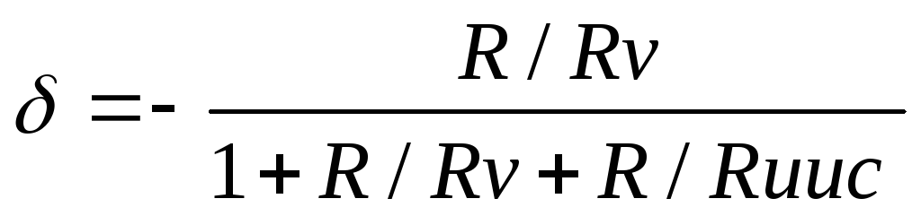 , i.e. the greater the internal resistance of the voltmeter, the smaller the measurement error.
DC voltage measurement can be performed by any DC voltage meters (magnetoelectric, electrodynamic, electromagnetic, electrostatic, analog and digital voltmeters.) The choice of a voltmeter is determined by the power of the measurement object and the required accuracy. The range of measured voltages ranges from fractions of microvolts to tens of kilovolts.
If the required accuracy can be achieved with devices of the electromechanical group, then this simple method of direct evaluation should be preferred. When measuring voltages with higher accuracy, instruments based on the comparison method should be used. With any method of measurement, analog and digital readings can be used.
Instruments for direct evaluation.
Magnetoelectric devices are used to check the modes of radio circuits and are used to measure voltages in devices of other systems. In addition, they are used as indicators. Voltmeters of the magnetoelectric system have a uniform scale, high accuracy, high sensitivity, but low input resistance.
Electrostatic voltmeters have the advantage of low consumption, independence from ambient temperature, high input resistance, and the disadvantages are an uneven scale and the danger of breakdown between the plates.
Electronic voltmeters are most widely used to measure direct voltage. They can be analog or digital.
Analog electronic DC voltmeters.
Unlike voltmeters of the electromechanical group, electronic DC voltmeters have a high input resistance and low current consumption from the measuring circuit. Figure M2-6 shows a block diagram of an analog electronic voltmeter.
Figure M2-6. Structural diagram of an analog electronic DC voltmeter.
The main elements are the input device, the DC amplifier and the measuring device of the magnetoelectric system. The input device contains input terminals, voltage divider, preamplifier. A high-resistance divider on resistors serves to expand the measurement limits. The DC amplifier serves to increase the sensitivity of the voltmeter and is a power amplifier of the measured voltage to the value necessary to create sufficient torque for the measuring device.
DC amplifiers are subject to such requirements as high linearity of the characteristic, constancy of the gain. The main technical characteristics of DC voltmeters are given in Table M2-3.
Table M2-3. Main technical characteristics of DC voltmeters.
|
Type, device name |
Range of measured voltages, V |
Basic measurement error, % |
|
B2-34, DC voltmeter, differential, digital |
0.01 mV - 1000V, subranges: | |
|
B2 - 36, DC voltmeter, digital |
| |
|
B2-38, DC digital nanovoltmeter |
|


Measurement of direct voltage with digital instruments.
Digital voltmeters are increasingly being used to measure voltages and currents. A simplified block diagram of a digital voltmeter is shown in Fig. M2-7.
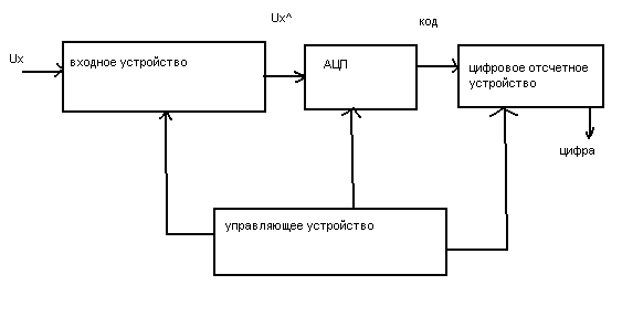
Figure M2-7. Block diagram of a digital voltmeter
The input device contains a voltage divider. An analog-to-digital converter (ADC) converts an analog signal into digital form and represents it as a digital code. The digital reading device records the measured value.
According to the type of ADC, digital voltmeters are divided into pulse-code and time-pulse. Since the ADC converts the DC signal into a digital code, digital voltmeters are considered DC voltage meters. To measure the alternating voltage, a converter is placed at the output of the voltmeter.
According to the type of measured value, digital instruments are divided into devices:
for measuring DC voltage;
for measuring AC voltage;
multimeters (universal voltmeters for measuring voltage, resistance, current)
Digital voltmeters usually have a high input resistance of more than 100 MΩ, measuring ranges of 100mV, 1V, 10V, 100V, 1000V. The sensitivity threshold on the range of 100 mV can be 10 µV.