
When an electrical device suddenly stops working, then its owner has a desire to independently deal with the malfunction and fix it. To do this, you need to make sure the integrity of the electrical circuit, the quality of connecting the connecting, serviceability of switches, switching devices and other elements.
This test consists of measuring the electrical resistance of the circuit. In the language of electricians, it is called "dialing".
How resistance is measured
Testing the resistance of any electrical circuit is based on the action through which a current is passed and. A stabilized voltage is applied to the input of the tested circuit. Usually chemical current sources are used for this:
- galvanic batteries;
- accumulators.
Less commonly, rectified voltage from an alternating current network is used.
If the circuit is intact and there are no breaks in it, then the current will overcome the total resistance of the circuit, and its value will be expressed by the ratio I = U / R
The simplest devices that electricians use to test resistance are called "dials". They are made according to the scheme below.
![]()
The batteries are soldered to one end from a flashlight, and to the other - a flexible electrical wire insulated with a crocodile clip at the end. A 2.5 square copper wire is attached to the second contact of the light bulb, which acts as a probe.
If you put the crocodile on the probe, the dialing circuit will close and current will flow through it. Its value is sufficient to warm up the filament and glow of the light bulb. The brightness of the light depends on:
- the state of the battery (with a large discharge, the voltage decreases);
- the resistance value of the circuit section.
If a resistor is placed between the probe and the crocodile, then the value of its resistance will affect the decrease in the glow of the light bulb. For example, a nominal filament current of 100 mA is generated by direct connection to a new battery. When, when checking the resistor, the current drops to 80 mA, then the glow will be clearly visible. With a significant increase in resistance or an open circuit, the light will go out.
With such a simple method, electricians check the integrity of wires and other sections of the circuit with a resistance value of up to several tens of ohms. With these measurements in the tested circuit, there should be no voltage from extraneous sources, which may be:
- charged capacitors;
- interference from neighboring electrical devices;
- chains connected in parallel with their own power supply.
Attention! The principle of the absence of voltage from an external source on the tested circuit should be carried out when measuring the resistance with any device. Otherwise, not only will an increased error appear, but the measuring device may fail.
If electricians mistakenly connect such dials to the phase and neutral conductors in the current wiring, then the filament of the light bulb from the passing current instantly receives a heat stroke, from which the glass balloon explodes and shatters into small fragments.
Similar errors when measuring with ohmmeters and multimeters lead to burnout of the conductive springs of the measuring heads or circuit components in new electronic models. Only expensive devices from leading manufacturers are equipped with protection against short circuits that occur in such situations. But is it worth checking them in this way?
The main disadvantage of this type of self-made dial-up is the inability to determine high-resistance resistances. Therefore, they are used only when testing low-resistance current circuits.
Multifunctional Voltage Indicators - Screwdrivers
Such devices are now being mass produced by the industry. They allow you to perform 5 main functions when working with electricity. One of them is the measurement of resistance, which is carried out by connecting the controlled area through a circuit created between a person's fingers.
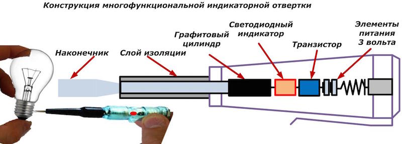
In the design of such multifunctional devices for measuring resistance, the following are used:
- batteries with a total voltage of 3 volts;
- bipolar transistor amplifying the indication current signal;
- LED, the glow of which indicates the passage of current through the tested section of the circuit;
- a screwdriver tip that serves as a contact pad.
Low-power voltage sources of these devices are capable of delivering only low currents to the circuit, which, when amplified by a transistor, reach only ten milliamperes. This is enough for the LED to glow.
However, they can check the integrity of fuses, filaments of light bulbs and similar simple devices. When measuring in complex circuits, multifunctional indicators do not work correctly because they are capable of ringing high-resistance sections created by an underestimated resistance of the environment. This main drawback often misleads electricians.
Ohmmeters
Their mass production in the USSR began in 1940.
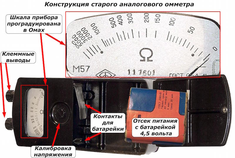
The design of the device includes:
- ebonite case with terminal leads for connecting wires to the measured resistance;
- 4.5 volt battery located in the power compartment with contact plates;
- ammeter, calibrated in ohms;
- an adjustment resistance for calibrating the voltage supplied to the circuit.
The polarity of the voltage applied to the circuit is marked on the body of the device near the output contacts with the signs "+" and "-".
Such an ohmmeter measures active resistance from 20 to 2000 ohms. In practice, electricians have to work not only in this range, but with higher and lower values. For this purpose they produce:
- megohmmeters of various capacities, issuing increased voltage to the tested circuit;
- measuring bridges allowing accurate measurements of low-resistance resistances.
Multimeters, testers
For the convenience of performing electrical measurements on the basis of an ohmmeter, combined devices work, which make it possible to evaluate the values of resistances on the scales:
- Ohms;
- kiloOhms;
- megaohms.
They have one precise measuring head, which, using shunts or additional resistances connected by a system of various mode switches, can work as:
- ohmmeter;
- ammeter;
- voltmeter.
Each mode has its own digital graduation in the corresponding units on the common scale. Three combined functions for measuring resistance, current and voltage gave rise to the name of such devices:
- a multimeter (formed from the words "a lot" and "measure");
- avometer (short for "ampere", "volt", "ohm", "measurement");
- tester (denotes the possibility of carrying out "tests").
An example of the design of the Ts4324 tester showing the positions of switching devices for measuring resistances in the 1kΩ range is shown in the photos below.
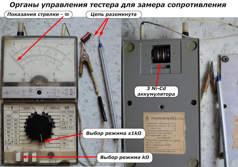
Such devices were used back in the 80s of the last century.
Modern devices work both on the basis of processing analog values and using digital technologies. In most models, they are equipped with a display on which the value of the measured parameter is immediately displayed. This is convenient because:
- taking readings is facilitated;
- no need to deal with the graduation of the scale;
- there is no need to engage in additional mathematical calculations.
However, the principle of applying voltage to the measured section of the circuit and measuring the amount of current flowing through the resistance remained the same in all devices. An electrician who understands well how Ohm's law works will always figure out the purpose of the switches and the methods of displaying information on any device, and will correctly measure the resistance.
How to check the health of the device
The basic rule for the accurate determination of resistance is the competent preparation of the measuring equipment for work and its use for its intended purpose.
At manufacturing enterprises, all electrical measuring devices, including ohmmeters, must be checked in a timely manner for:
- the integrity of the insulation and have a stamp of the testing laboratory confirming the permit for operation in existing electrical installations;
- correct operation in the declared accuracy class and be certified by the verifier.
For household appliances, these issues should be dealt with by the owner by handing over his tester to the appropriate laboratories.
Before each resistance measurement, you must:
- set the dial gauge in a horizontal plane and fix it;
- check the initial setting of the arrow to zero;
- calibrate the voltage source;
- put all switches of the device in the appropriate measurement mode;
- evaluate the serviceability of connecting the connecting wires and their integrity, for which to close the ends and check the reaction of the arrow or the digital display of resistance on the display.
And always remember to check that there is no voltage in the test area before starting the measurement.
How to call the main elements of the electrical circuit
When monitoring the resistance value of any section of the circuit, the component under test is connected to the output terminals of the measuring device, which is switched to the ohmmeter mode.
Wires and cables
A working metal core has a resistance close to zero, and the insulating layer on it tends to infinity. This rule is taken as the basis for checking wires and cables.
Inside electrical wiring, there are cable lines and wires connected in various ways. Before starting the measurement, each cable and wire must be disconnected from both sides, otherwise errors may occur due to additionally connected chains.
If it is necessary to evaluate the assembly of the electrical circuit, then check:
- the integrity of the lived;
- the absence of extraneous chains that may arise in case of insulation faults.
In the first case, they work with an ohmmeter, and in the second, with a megohmmeter of a certain voltage and power.
When voltage is supplied to one core from an ohmmeter, the measuring head on a good wire will show "0" Ohm.
Existing cables, which are subject to continuity, can be laid in the ground and stretched for several hundred meters. Removing the opposite ends in this way complicates the measurement. The way out of this situation is to lengthen the measuring wire due to:
- using a pre-tested and marked core;
- connecting one end of an ohmmeter and the opposite side of the wire to ground loops to create a current path through the ground.
When looking for insulation faults that led to short circuits in the network, it is better to work with a megohmmeter and consistently measure the resistance of each core relative to all the others and to the ground.
For cables for different purposes, the rated insulation resistance can range from 0.5 to several megohms. If places of insulation failure are identified, the wires are rejected and taken out of service.
Fuse
Since this element is a short piece of wire placed in a dielectric case, its good condition will correspond to the reading of 0 on the ohmmeter scale, and the broken one - to ∞.
Resistor
It is made to work in circuits with various values of electrical resistance, which can be from a fraction of Ohm to several megohms. Therefore, when checking resistors, all modes of the ohmmeter are used.
Diode
The main purpose of this semiconductor element is to pass current in one direction and block in the other. Since an ohmmeter, when connected to the circuit, gives out a current of a certain polarity, then a working diode with a direct connection of the device will have 0 ohms, and with the opposite - ∞.
If, during forward and reverse switching on, the ohmmeter shows 0 or ∞, then the diode is broken or burned out. It needs to be changed.
Light-emitting diode
In practical electrical engineering, there are both single and complex LED designs. They work on the principle of a conventional diode, additionally emitting light when current passes through it. When the current is blocked, there will be no glow.
At first glance, the LED test technology is no different from the previous method. But there is a peculiarity here: the nominal current of most LEDs is about 10 mA. If the ohmmeter gives a much lower value, then the glow will simply not be visible. This is most often inherent in modern economical and expensive multimeters.
It is also not recommended to significantly exceed the current through the LED with a self-made continuity. The semiconductor layer may not withstand increased thermal conditions. Therefore, during such checks, it is necessary to know the technical capabilities of the measuring device and to limit the test time.
It is best to use an adjustable source with the ability to gradually increase the current to 10 mA to test the LED.
Inductor, transformer, electric motor, choke
These devices are performed by winding an insulated wire onto a coil, which is placed inside the magnetic circuit. Each turn of the winding, when current passes, creates an electromagnetic field around itself, which is added to the fields of the remaining turns.
If the insulation of the wires between the turns is broken, then an electrical contact occurs (turn-to-turn closure), which sharply reduces the total inductance. When such windings ring, their resistance changes so slightly that it is impossible to detect such a malfunction by measuring with an ohmmeter.
Turn-to-turn closures define:
- switching on under load in alternating current circuits;
- by taking the current-voltage characteristic.
The ohmmeter method can only determine a wire break or a break in the contact connection in the winding.
Heating element
Heating elements work in electric kettles, electric heating boilers, heaters. They are made of nichrome wire, placed in a metal case and connected to the contact legs.
When measuring a serviceable heating element, the resistance reading on the ohmmeter will have a small value, which can range from several units to tens of ohms (depending on the design). Thread breakage is indicated by the ∞ indication.
For powerful heaters, several heating elements are used, which are connected in parallel, and the terminals are placed side by side. In such cases, it is necessary to carefully understand the accessory of the terminal leads.