
From this article, the reader will learn how to quickly and correctly mount and independently connect all devices and program keys. Diagrams of the most common connections are provided. As well as a list of tools and materials that will be needed for this.
The standard set of devices that are included in the video intercom kit is as follows:
- A monitor with a handset or speakerphone, which is also a control device;
- The call panel in the anti-vandal case;
- Electromagnetic or electromechanical lock;
- Power supply (optional redundant power supply highly recommended);
- BUZ - lock control unit;
- Additional cameras can optionally be added.
Tools and materials
To perform the video intercom installation, the following set of tools is required:
- Perforator with a set of drills, a peak and shovels for wall chasing;
- Drill and or screwdriver;
- Angle grinder with a diamond disc for metal;
- Screwdriwer set;
- Pliers;
- Hammer;
- Container for mixing putty and spatula.
The list and quantity of materials used depends on the method of cable laying, remoteness and placement of actuators and other equipment. In most cases, the following materials are needed:
- UTP wire is more commonly known as twisted pair. Preferably with foil insulation;
- Two-wire wire for power supply;
- RCD residual current device, since the power wire will be partially mounted outside;
- Sockets and plugs;
- Flexible adapter to protect wires from chafing;
- Corrugated electrical pipes;
- A set of fastening clips for fixing the corrugations;
- Gypsum, alabaster or putty.
Installing a video intercom monitor
Please note that the device is powered by 220 V, so there must be a socket within reach. Ideally, the power cable, lock control and data transmission from the call panel should be brought into one socket on top of which the device will be installed.
The installation height should approximately correspond to the eye level of an adult 1.4-1.5 m.
Call panel installation
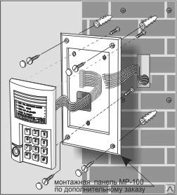
The call panel is mounted mainly on fixed building structures: the wall of the house or the main column of the gate. It is strongly not recommended to install the device on mobile devices - wicket gates or doors, as constant shaking can displace the lens inside the case. Installation is carried out as follows:
- The rear cover is removed from the calling panel;
- Drilling holes are marked through the mounting holes;
- All marked places are drilled and an additional through hole for removing the wire;
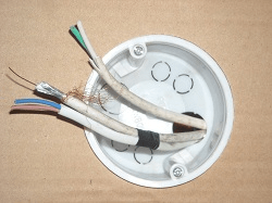
- The wire is connected to the contact strip of the call panel in accordance with Scheme 1 and is brought into the house to the control device;
- The wire brought into the yard is connected to the contacts of the electromechanical lock (depending on the model of the device).
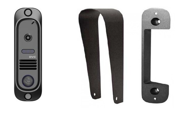
After checking all the connections, the call panel is attached to the base with special self-tapping screws or “secret” screws that cannot be removed with a simple screwdriver. Depending on the direction of lighting, it is recommended to use a canopy and a corner bracket.
Installation scheme of the electromagnetic lock
The key device that protects the coil of an electromagnetic lock from a constant supply of voltage is the BUZ - an electromechanical lock control unit. If it is not included in the standard set of the video intercom, then it is necessary to purchase it, since without it the electromagnetic coil of the locking device will quickly fail.
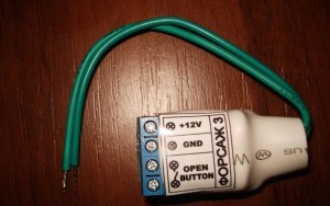
Depending on the case of which device the BUZ will be placed in, the connection can be made according to the following schemes:
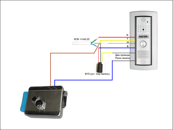
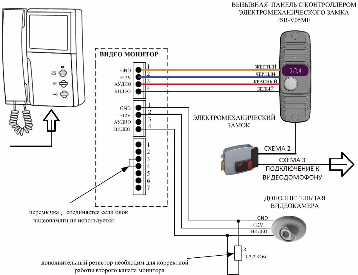
The cable from the video intercom to the electromechanical lock is supplied with a two-wire 12V+ and GND. In this case, the lock is controlled from the calling panel board.
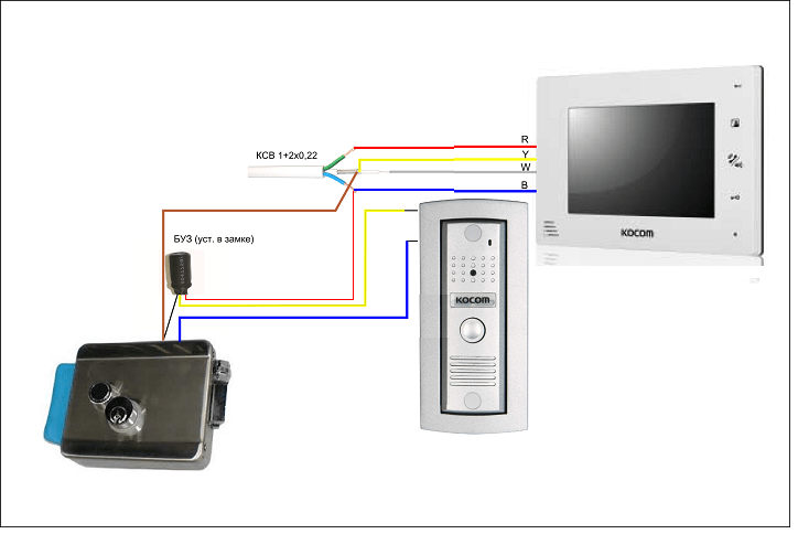
In this case, 4 wires are suitable from the video panel to the electromagnetic lock. In order to be able to open the lock from the call panel, the corresponding cables are connected in parallel to the BUZ from it, as indicated in Scheme 3.
Connecting the power supply
According to fire codes and regulations, all electromechanical locks, when the power is turned off, must switch to the open state or release the locking mechanisms for mechanical / manual opening. With such features of functioning, it is enough for attackers to de-energize the house for the lock to open. To prevent unauthorized access, it is advisable to equip the video intercom with an uninterruptible power supply.
Most video intercom kits provide a power supply only for the video panel. In addition, if a model was purchased with the ability to connect additional devices (, calling panels), then a powerful centralized power supply is required that will ensure operation.
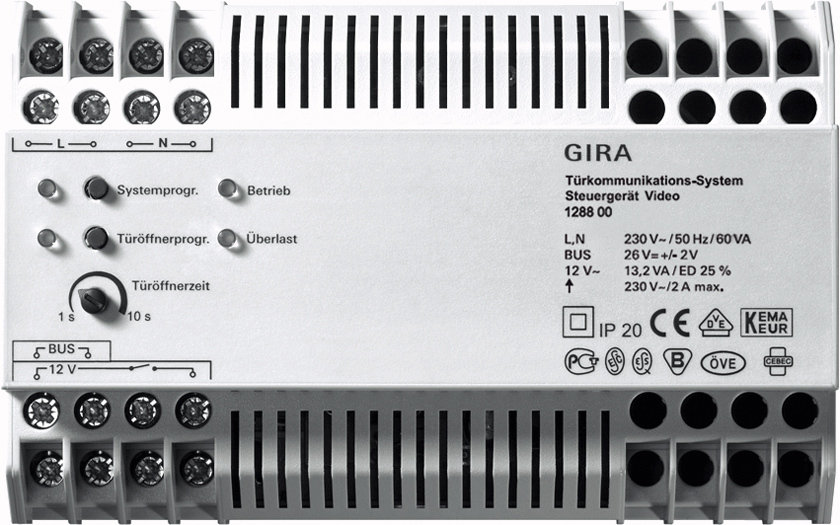
The choice of power of such a device is quite simple. It is necessary to add up the total load of all used devices and add 20% to the resulting number. The connection is made from the contact strip on the left side of the block. A pair of cables is routed to each device.
Key programming
Before starting the operation of the video intercom, it is necessary to write the key codes into its memory. Regardless of the type of keys or magnetic cards and the model of the reader, each set must have a master key. It must be programmed first and not used. This is done quite simply. After turning on the video intercom for the first time, the device will emit a sound and light signal. At this time, it is necessary to touch one of the keys to the contact reader and hold until a signal is heard. In the future, it is this key that will give access to the administrative functions of the device: writing blocking keys, changing system settings, etc.