
Tester, avometer, multimeter - these are the names of the same measuring device. It allows you to measure with acceptable accuracy the main electrical parameters - voltage, current and resistance. Information is displayed either on an arrow board, like in analog models of past years, or on a digital display, like in modern models.
Regardless of the type of information display, a power source is installed in the tester. Usually these are two 1.5 V finger batteries. Any tester has at least two terminals to which the probes are connected. They are used to connect the tester to two points of the electrical circuit, the parameters of which are being tested. Voltage and current measurement does not require battery power consumption.
But the so-called "ringing" is based on the creation of voltage and current between the touch points of the tester probes. Therefore, first of all, when ringing electrical circuits, batteries with sufficient energy are needed. This is a measurement of the resistance of an electrical circuit. And if it is not there, and the probes are in contact with each other, then the value of the measured resistance is zero.
Therefore, if the readings on the display are different from zero, the tester must be calibrated with the regulator for adjustment. It is best to set the measurement range in Ohms. In this mode, the maximum power consumption of the batteries is obtained. If you can't get zero on the scoreboard, then they need to be replaced. In an analog instrument, you can remove the batteries and check them in current measurement mode.
Usually one of them is discharged more than the other. Therefore, you can replace the most discharged battery with a fresh one and re-check the zero setting in the resistance measurement range in Ohms. If everything worked out well, you can start dialing. Although, if you do not need to measure any resistance values, it is not necessary to check the zero setting and the condition of the batteries.
When checking the electrical circuit, it is necessary to make sure that the electrical current generated by the tester flows only through this circuit. Otherwise, the scoreboard will display values that take into account adjacent nets. This is possible, for example, in a printed circuit board. Therefore, it is possible to correctly check or measure the resistance of only one element installed in it and only with one output sealed from the board.
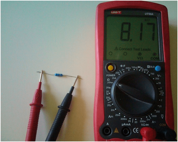
Ringing resistor
If this element turns out to be a resistor with an unknown resistance, for example, color-coded, and the tester has several resistance measurement ranges, you can first set any resistance measurement range. Then touch the terminals of the resistor with the probes and look at the scoreboard. If the tester is analog and the range is selected unsuccessfully, the arrow will be close to the extreme positions.
In this case, it is necessary to switch to another range, in which the arrow will be close to the middle of the scoreboard. After that, you need to clarify the zero setting for this range and measure the resistance of the resistor. In approximately the same way, the resistor is ringing with a digital tester. The difference is only in the readings on the scoreboard in numbers and it may not be necessary to check the zero setting, since the digital testers are modernized.
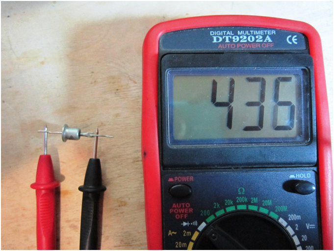
Diode ringing
Diodes come in several varieties. They are united by the presence of only two conclusions. But at the same time, they perform functions different from each other. For example, ringing a tunnel diode with a tester does not make sense, since it will simply measure the resistance without the possibility of checking its compliance with its purpose. The same applies to zener diodes and LEDs.
They can be tested as intact, but they do not match the parameters. Therefore, only the rectifier diodes are correctly checked with a tester. In this case, you can identify a faulty diode and determine the anode and cathode of a working one. If, by touching the terminals in the kilo-ohm measurement mode, there are no readings on the display, and when the probes are changed in places, the resistance reading appears on the display, the diode is operational.
In this case, the anode will correspond to the “plus” probe, and the cathode to the “minus” probe when readings on the display. The readings on the scoreboard, regardless of the change in the probes in places, indicate that the diode is damaged. But this is true only with full confidence that this is a rectifier diode. Otherwise, it may be a working zener diode or a tunnel diode.
The same can be the case when the breakage is indicated on the board. That is, when the readings on the display are very high resistance, at any position of the probes, only a rectifier diode can be faulty. A dynistor - a switching diode switched on by a voltage of a certain magnitude - can be serviceable.
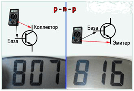
Transistor ringing
It is recommended to check only bipolar transistors with a tester. For field-effect transistors, the gate junction can be damaged during testing due to its high sensitivity to static electricity. To check, you need to free the collector and emitter from the connections. Since transistors are sensitive to overheating when soldering, do not remove them from the board.
It is better to break the electrical circuit by unsoldering one of the terminals of the diode or resistor connected to this transistor. All bipolar transistors have a collector, base and emitter, regardless of their design. If the transistor is working properly, the ringing of the base-emitter and base-collector transitions is obtained as in two diodes with a common terminal. It is the base. In this case, the collector-emitter junction is usually serviceable and shows high resistance at any position of the probes.
Therefore, you need to find the base first. To do this, one probe must be connected to any output, and the other must be connected alternately with the two remaining ones. And while looking at the scoreboard. If the readings differ significantly, go to the next conclusion. If the readings differ in this case, you must go to the last conclusion.
With different readings for all three conclusions, it is necessary to swap the probes and repeat the test. If it was not possible to find a conclusion, relative to which the other two show almost the same resistance, then the transistor is not working properly. If it works, it means that the database has been found. The plus probe at the base is an NPN transistor. Negative - pnp transistor.
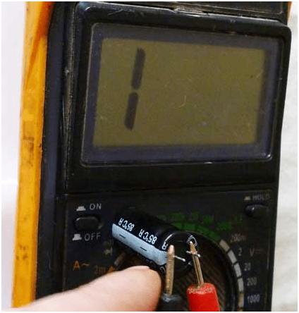
Condenser ringing
The capacitor is also checked with a tester. You can check the condition of the insulation between the plates and estimate the capacity. But the latter is possible only at sufficiently large capacitance values, starting from microfarad units. In this case, it is better to use a tester with an arrow board, since the movement of the arrow is much more noticeable than a quick change of numbers.
When ringing, a good capacitor shows an open in the megohm measurement range. But this does not apply to polar electrolytic capacitors. When checking them, it is necessary to observe the polarity, touching the positive probe to the positive terminal, and the negative probe to the negative terminal of the capacitor. And at the same time on the scoreboard there will be a reading of resistance. The bigger it is, the better. The lower the leakage current.
If the measured resistance between the terminals is small and the display shows tens of kilo-ohms or less, the capacitor is damaged. When you touch the terminals of a capacitor with a capacity of microfarads or more, the readings on the board start with values close to zero and then increase. This is due to the filling of the electrical capacity with the energy of the tester's batteries. At the same time, it is a source of EMF with a certain internal resistance. It is minimal when using a range in ohms and increases with further range switching.
Therefore, for a specific capacitor, it is necessary to select the optimal resistance measurement range. Then you can compare several capacitors in terms of capacity. A slower movement of the arrow corresponds to a larger value of the capacity.
The tester is indispensable for evaluating electrical circuits from one or more elements. But you should not leave the tester in the same state after such checks. You must either turn it off, or switch it to the current or voltage measurement mode. This will extend the life of its batteries.