
When carrying out renovation work in the kitchen, as a rule, a new kitchen unit, oven and hob are installed. At the moment, there are two modifications of the oven and hob:
- independent devices;
- complex headset.
Integrated hob and oven
The main difference is that independent devices are directly an oven without a hob, which can be installed anywhere.
Complex devices include an oven and hob in one housing with controls on the front of the appliance. In appearance, they resemble classic electric stoves, where the oven is located at the bottom, and the hob is on top.
Cabinet location
To connect, it is necessary to prepare a workplace for the oven, namely a special niche in the kitchen unit, observing the following parameters:
- The presence of distortions of the installation surface is not allowed. An uneven position of the oven results in an uneven distribution of heat energy inside the appliance, which, in turn, can lead to breakdown.
- The presence of gaps between the surface of the kitchen set and the oven is mandatory. The reason is that during operation, the body of the device heats up and an abundant release of thermal energy occurs.
Distances from the walls of the niche to the cabinet:
- from the side wall to the oven body - 5 cm;
- from the bottom to the base of the device 8-10 cm;
- clearance for ventilation of 4 cm between the wall and the back cover.
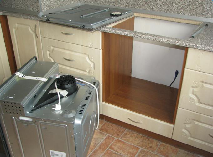
Preparing the place for installing the oven
TOcable and circuit breaker
Due to the high power consumption of devices, the power of which starts from three kilowatts and more, it is recommended to supply the cabinet with a separate cable. For this purpose, a three-core wire is suitable (the presence of a grounding yellow-green conductor is required). The cable cross-section is selected based on the nominal power of the oven.
When the power of the electric stove is above 3.5 kW, a cable with a cross section of 3x4mm 2 and a socket with a circuit breaker of at least 32 amperes of operating current are selected.
Cabinet connection
After completing the installation stage of wiring and sockets, it will not be difficult to connect the cabinet. The device is connected using a plug with grounding contacts.
It is recommended to connect using a separate circuit breaker due to the high power of the electrical appliance. To ensure safety, an RCD (Residual Current Device) or a residual current circuit breaker must be used.
Depending on the design, the power supply to the cabinet can be supplied with a plug installed by the manufacturer or with a direct connection.
When switching without using a plug and socket, a wire is laid from the switchboard, and the heating surface is connected directly to the factory contacts.
The second method of supplying voltage to the cabinet is more reliable, due to the absence of additional transition resistance between the plug and the socket contacts.
If the plug for the cabinet is not provided by the manufacturer, you will need:
- a piece of cable from the outlet to the cabinet;
- power plug with grounding blades.
Work order:
- To connect the cable, the plug is unscrewed, and the wire is fixed to the terminal clamps.
- The working position is restored.
- The plug connects to the socket, as a result the cabinet is ready for use.
To connect the oven, you can use a European socket with grounding contacts (if the load does not exceed 16 amperes) or a specialized power outlet for an electric stove. The choice is made depending on the power of the oven.
The yellow-green wire must be put on a separate terminal in the cabinet, designed for grounding electrical equipment. The connection points of the main wires (phase and zero) are switched to free contacts provided by the manufacturer.
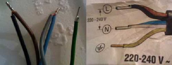
Color scheme of the cable for connecting the oven
Hob fork
A three-core copper cable must be used to supply power to the hob. For 380 volts, a five-wire wire is used.
The cable cross-section is selected according to the load and the calculation of the operating current, but not less than 4 mm 2, the circuit breaker is selected for 32 A. When using a 6 mm 2 cable, the circuit breaker is used for 40 A.
The peculiarity of the hob is that the surface heats up at lightning speed. This phenomenon is due to the high power consumption (up to 7 kW).
If there is a stationary outlet for powering the electric stove, it will not be difficult to connect.
The hob plug is connected as follows:
- A 220-volt AC power plug is purchased.
- The protective case is removed.
There are six connection pins inside the power plug. Terminals one, two and three are designed to connect the phase conductor (L), as a rule, they are connected by a jumper. Contacts number four and five are designed to connect the neutral wire (N). Terminal number six is for a grounding conductor.
- When using a 220 volt socket, the phase wire is connected to pin one (L) and a jumper is installed between the first three terminals.
- The neutral conductor is connected to the fourth or fifth terminal (N).
- The sixth terminal is designed for a protective earth connection.
If the phase conductor is incorrectly connected, the protection (RCD or differential circuit breaker) will constantly work.
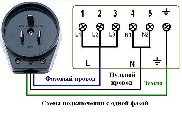
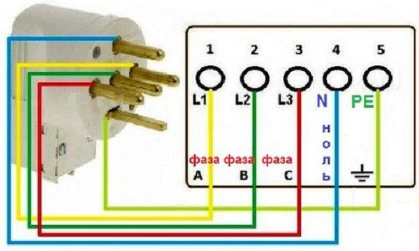
Connection diagram of the power plug for the 220 volt hob
The 380 volt power plug is connected as follows:
- The plug cover is removed.
- Phase conductors are connected to contacts (1), (2), (3) (marked with the letter L in the figure).
- The neutral wire is connected to terminals (4) or (5) (N1-N2).
- Ground is connected to the sixth pin.
Hob sockets
The 220 volt socket for the hob differs in the location and shape of the plug holes. These switching devices are made in such a way as to exclude the possibility of incorrect connection of the phase and protective conductor, in the form of a hole in the upper part of the outlet, which is different from the rest in shape and diameter.
The 380 volt sockets is a stationary switching device with five sockets, designed for a three-phase load, a neutral conductor and a protective earth.
Before purchasing this outlet, you must make sure that the plug fits into the contact holes without force or deformation of the current-carrying pins.
Connection strand:
- The supply cable is de-energized.
- The indicator checks the absence of voltage on live parts.
- Opposite phase conductors are connected to contacts numbered from first to third (L1-L3) inclusively.
The phase sequence is irrelevant for the hob.
- The neutral conductor is connected to the pin connector marked (N).
- The ground wire connects to the grounding lug (on some receptacles, it is numbered six or indicated by a tree icon).
Power supply to the hob
Depending on the manufacturer, there are several types of heating surface supply:
- connection of 380 volts using two phase conductors;
- for a 220 volt network;
- the possibility of switching three phases at 380 volts.
Before starting the connection, it is necessary to check the diagram with the terminal box of the device and the instructions for determining the factory assembly.
- Socket contacts with numbers from the first to the third (L1-L3) inclusive are used for switching the phase wire.
- Terminal numbers five and six (N1-N2) are needed to connect the neutral conductor.
- For switching the protective grounding of the hob, there is a separate bolted socket contact with a corresponding “tree” icon.
Hob power connection diagram
With a suitable 220 volt power supply to the hob, there is no need to interfere with the factory circuit, it is enough to connect the conductors by color and terminal numbers.
A brown wire is used to connect the phase conductor. The blue core is used for zero switching. The green-yellow wire is used for the protective grounding of the hob.
For many new buildings and private houses, the power input is made with a three-phase cable with an alternating voltage of 380 volts.
Two-phase connection:
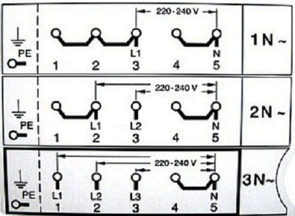
- For a two-phase connection, remove the jumper between the second and third contact in the terminal box of the hob.
- Opposite phase conductors are connected to the second and third terminals (L1-L2) as shown in the figure above, marked 2N.
- The neutral conductor is connected to the fourth terminal.
- The protective earth is installed on a special screw connection on the hob.
With such a power supply, an accurate calculation of the power of the entire power supply of the room is necessary due to the use of two independent phases. If the load is not properly distributed, a "skew" may occur, which will lead to different voltage values on each individual phase.
Three-phase switching of the hob:
- When using a three-phase connection, remove the jumpers from contacts (1), (2), (3) (L1-L3) marked 3N.
- The phase conductors are connected to the hob and the plug to the terminals (L1-L3), the phase sequence does not matter.
- For switching the neutral wire, terminal four or five (N) is used. It is recommended to use the far terminal number five for safety reasons.
- The grounding connection is carried out in a special socket with a bolt connection and the corresponding marking.
When using 380 volts, special care is required when connecting. If at least one phase conductor is incorrectly connected, the hob may fail or be burned due to a short circuit.
Hob connection. Video
You can learn about the nuances of connecting the hob from this video.
For switching the hob and oven, accurate calculations of the load of the conductors and the choice of protective equipment will be required. It is strongly not recommended to use these devices without special devices for protection against leakage and short circuit currents. To complete the work, it is recommended to use the services of professionals who will calculate the load, protective equipment and select the necessary accessories.