
Switches are used to turn on the lighting, and buttons and switches are used for household electrical appliances. This electrical equipment has one thing in common: they consume little power. And also - they are not switched on remotely or by automation devices. These tasks are solved with the help of magnetic starters.
Magnetic starter circuit. Device
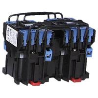
The starter consists of two parts located in one housing: a control electromagnet and a contact system.
The control solenoid includes a coil with a magnetic circuit, which includes a movable and a fixed part, held in the open state by a spring. When voltage is applied to the coil, the moving part of the magnetic circuit is attracted to the stationary part. The moving part is mechanically connected to the contact system.
The contact system includes movable and fixed groups of contacts. When voltage is applied to the starter coil, the magnetic circuit attracts the moving contacts to the fixed ones and the power circuits are closed. When the voltage is removed from the coil, under the action of a spring, the movable part of the magnetic circuit, together with the contacts, are brought to their original position.
An additional contact group is added to the power contacts of the starter, designed for use in control circuits. Its contacts are normally open (designated by the numbers "13" and "14") or normally closed ("23" and "24").
Electrical characteristics of magnetic starters
Rated starter current- this is the current that the power contacts can withstand for a long time. For some models of obsolete starters, for different current ranges, the overall dimensions or “value” change.
Rated voltage- supply voltage, which withstands the insulation between the power contacts.
Control coil voltage- operating voltage at which the starter control coil operates. Starters are available with coils operating from a DC or AC mains.
The starter control is not necessarily powered by the voltage of the power circuits; in some cases, the control circuits are independently powered. Therefore, control coils are available for a wide range of voltages.
| Alternating current | 12 | 36 | 48 | 110 | 220 | 380 |
| D.C | 12 | 36 | 48 | 110 | 220 |
Reversing magnetic starter, push-button station
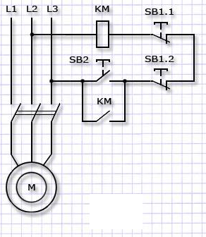
The most common application of starters is motor control. Initially, the name of the device is derived from the word "start". The circuits use additional contacts built into the case: to pick up the command from the "Start" button. Normally closed contacts of the "Stop" button break the power supply circuit of the coil, and the starter disappears.
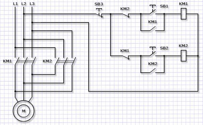
Issued reversible blocks incorporating two conventional starters connected electrically and mechanically. Mechanical interlock does not allow them to turn on at the same time. Electrical connections provide two-phase reversal when operating different starters, as well as the elimination of the possibility of supplying power to both control coils at the same time.
For ease of installation, starters produce in housings together with control buttons. To connect, just connect the power cable and the outgoing cable to them.
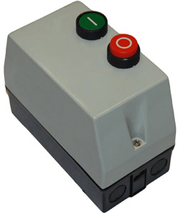
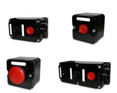
In other cases, to control the work are used pushbutton stations, switching the control coil circuit and connected to the starter by a control cable. For conventional starters, two buttons are used, combined in one housing - "Start" and "Stop", for reversing - three: "Forward", "Back" and "Stop". The "Stop" button for quick shutdown in the event of an accident or danger is mushroom-shaped.
Depending on the purpose, the starters are made with three or four poles. But there are also devices that have one or two poles.
Manufacturers complement the line of manufactured devices accessories expanding their capabilities. These include:
- additional contact blocks that allow you to connect signal lamps to the control circuit and generate commands depending on the state of the starter for the operation of other devices;
- time delay blocks that delay the operation or shutdown of the starter;
- sets of accessories that turn two starters into a reversing assembly;
- pads that allow you to connect larger cables to the starter.
To protect electric motors from overloads, together with starters, thermal relays. Manufacturers produce them for the corresponding models of devices. The thermal relay contains a contact that opens when triggered and breaks the power supply circuit of the starter coil. To re-enable the contact must be returned to its original position by pressing the button on the body. To protect against short circuits, a circuit breaker is installed in front of the starter, which is detuned from the starting currents of the electric motor.