
Security and protection of property in our turbulent age has become an integral part of our lives.
In contact with
How to exclude random guests, how to keep hooligans and criminals out of your home? What is better lock, peephole, concierge, intercom or video surveillance, security?
If these questions are answered correctly, then this article will help you understand the features of its use.
The article provides a descriptive diagram of connecting an electric lock to a video intercom, sets out installation and operation issues.
 Video intercom is an intercom with the ability to display the visitor and provide him with access to the premises without the need for direct contact with him.
Currently, a large number of variants of these devices have been developed.
They may vary:
- display type: color, black and white, lamp, liquid crystal;
- sound playback type: handset or loud playback, as well as from a mobile phone with 3G support;
- keyboard type: touch or tactile;
- type of lock: electromechanical or electromagnetic.
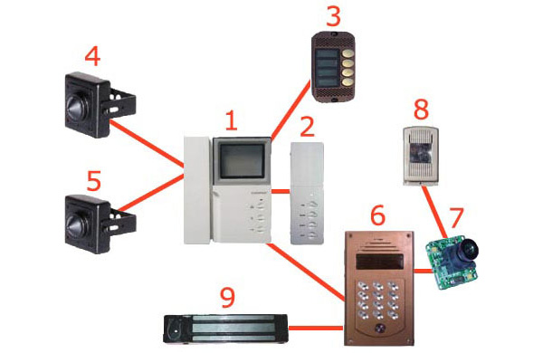
The connection diagram consists of:
- directly video intercom with monitor and control keys;
- with button, camera and microphone;
- electric or electromagnetic lock;
- electromagnetic relay;
- power supply 12 V;
- connecting wires.
Basic connections
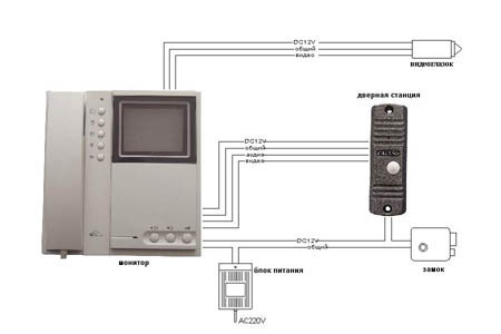 Consider connecting with an electric lock.
The video intercom is connected to the call panel with four wires: two wires for connecting power, and audio.
To avoid confusion, the terminal panel of the video intercom, as a rule, is marked with color and symbolic markings.
Connecting wires should be selected with the same color coding for the insulating braid.
The call panel, in addition to color wires for connecting to a video intercom, also has a pair of additional wires for connecting to an electric or electromagnetic lock.
An electric or electromagnetic lock has only two wires for connecting to a power source. Connecting power to the lock corresponds to the closed state of the lock, removing power - to the opposite event, i.e. open state.
The electromagnetic relay has a control winding and a contact group with a reversible contact. The relay control winding is powered by the call panel. The contact group connects and removes power from the electro (electromagnetic) lock by closing and opening the flipped contact.
It is possible to use automotive relays with a removable contact box.
Bringing access keys to the reader, they are programmed. After some time, the reader is taken out of the recording mode, the lock is blocked, and the presentation of the keys leads to its unlocking.
The controller has the ability to write keys without a master key. When the power is off, the jumper (jumper) becomes in position 3. The power is connected, the controller is ready to read the access keys, the access key is presented, the information is read, the power is removed.
The jumper is removed, the controller is put into operation, power is connected. The controller is ready for use again.
Electromagnetic lock operation and reset
 The video intercom is turned on. At the same time, the power supply indicator lights up. A call is made from the call panel by briefly pressing the button.
The incoming signal of pressing the button by the video intercom is converted into an audio signal. Using the lock release button on the video intercom, the sound of the signal is interrupted, the relay power circuit is opened, and the door opens.
The switched off state of the electromagnetic lock is held by the relay, which receives the corresponding signal for some holding time from the calling panel.
After this delay time has elapsed, the electromagnetic relay is activated again and the lock switches to the closed state.
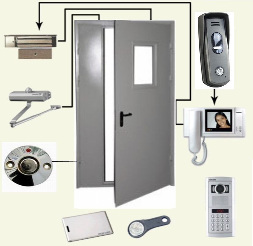 It is necessary to select places for and the call panel and install them.
The electromagnetic lock is located on the door. It should be positioned so that the attracted panel is on the movable side of the door, and the lock is on the fixed side.
The connecting wires are laid in the wall in advance, a hidden gasket is made or they are hidden in a metal corrugation. performed in accordance with the wiring diagram.
Constant call progress: to solve this problem, it is proposed to check the absence of a short circuit between the audio line (usually yellow wire) and the body (black wire);
No call: This problem is usually caused by an open audio line or case;
No video, accompanied by no sound: the problem is usually caused by an open or short in the power supply (red wire) or a broken case (black wire);
No picture, no sound. In this case, there may be an open or short in the video line (white wire).
In other cases of malfunctions or malfunctions of the device, in order to preserve its integrity and installation, it is recommended to seek advice and assistance from representatives of the company involved in its direct maintenance.
Currently, the market is saturated with a significant number of devices that provide remote access to the premises.
The systems of collective use are easier to maintain and operate than the systems of individual use.
However, given the basic patterns of operation and connection rules, you can install and maintain them yourself.
In contact with
See inaccuracies, incomplete or incorrect information? Do you know how to make an article better?
Would you like to suggest photos for publication on a topic?
Please help us make the site better! Leave a message and your contacts in the comments - we will contact you and together we will make the publication better!