
For an electrician, switching equipment is one of the main devices that you have to work with. Circuit breakers carry both switching and protective roles. Not a single modern electrical panel is complete without automatic machines. In this article, we will look at how the circuit breaker is designed and works.
Definition
A circuit breaker is a switching device designed to protect cables from critical currents. This is necessary in order to avoid damage to the conductive cores of wires and cables in the event of phase-to-phase faults and ground faults.
Important: The main task of the circuit breaker is to protect the cable line from the consequences of the flow of short circuit currents.
The main characteristics of circuit breakers are:
Rated current (1, 2, 3, 4, 5, 6, 8, 10, 13, 16, 20, 25, 32, 35, 40, 50, 63, 80, 100, 125, 160, 250, 400, 630 , 1000, 1600, 2500, 4000, 6300);
Switching voltage;
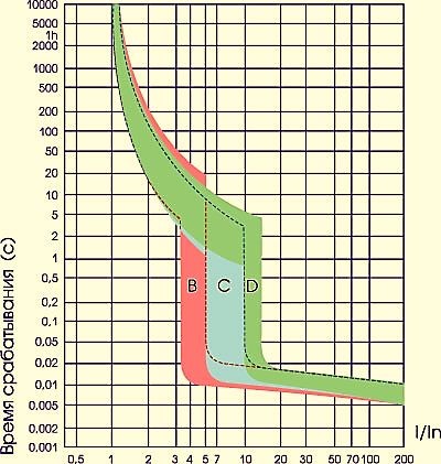
Time current characteristic.
The machines are most widely used in household and industrial power networks with a voltage of 220/380 volts. Voltages are given for domestic electrical networks. Abroad, they may differ. Relay circuits and current transformers are used in high voltage lines. reflects after what period of time and at what value of current relative to the nominal value the opening of its contacts will occur. An example of it is shown in the figure below:
Principle of operation
The circuit breaker (AB) is a switching device that contains two types of protection:
Electromagnetic release.
Thermal release.
Each of them performs the same work - opening power contacts, but under different conditions. Let's consider them in more detail.
When currents flow through the machine below the nominal value, its contacts will be closed indefinitely. But with a slight excess of current, the thermal release, represented by a bimetallic plate, will open them.
The greater the current flowing through the contacts of the circuit breaker, the faster the heating of the bimetallic plate will occur - this is described during the current characteristic and is indicated by the speed of the machine (a letter near the rated current in the marking). Depending on how overloaded the machine is with current, the time of its shutdown depends, it can be tens of minutes, or it can be units of seconds.
The electromagnetic release trips with a rapid increase in current. The magnitude of the current of its operation is orders of magnitude higher than the rated current.
Hence the question arises: "So why does the machine need two protections, if you can simply design it so that it turns off immediately when the rated current is exceeded?"
There are two answers to this question:
1. The presence of two protections increases the reliability of the system as a whole.
2. When connecting devices to the circuit breaker, the current of which changes during start-up and operation so that false positives do not occur. For example, for electric motors, the starting current can be ten times higher than the rated current, and also during their operation short-term overloads on the shaft can occur (for example, a lathe). Then, during a protracted start, the machine will also knock out.
Device
The circuit breaker consists of:
Cases (in the figure - 6).
Terminals for connecting conductive wires (in the figure - 2).
Power contacts (in the figure - 3, 4).
Arc chute (in the figure - 8).
Levers connected to buttons or checkboxes to turn it on and off (closing and opening contacts) (in the figure - 1 and what it is connected to).
Thermal disconnector (in the figure - 5).
Electromagnetic disconnector (in the figure - 7).
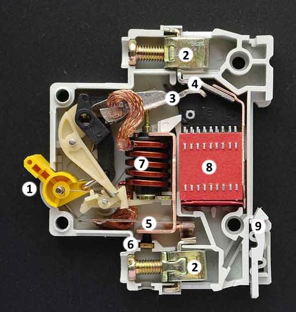
The number 9 indicates the latch for mounting on a DIN rail.
Power is connected to the terminals (usually the top, in practice it does not really matter), and the load is connected to the terminals on the opposite side. The current passes through the power contacts, the coil of the electromagnetic disconnector, the thermal disconnector.
Electromagnetic protection is made in the form of a coil of copper wire, it is wound on a frame, inside of which there is a movable core. The coil contains from several units to a couple of tens of turns, depending on its rated current. In this case, the lower the rated current, the more turns and the smaller the cross section of the coil wire.
When current flows through the coil, a magnetic field is formed around it, which affects the movable core inside. As a result, he extends and pushes the lever, as a result of which the power contacts open. If you look at the figure, then the lever is below the coil, and when its core is lowered, the mechanism is activated.
Thermal protection is needed for prolonged overcurrent. It is a bimetallic plate that bends to one side when heated. When a critical state is reached, she pushes the lever, and the contacts are disconnected. The arc chute is needed to extinguish the arc that occurs due to the opening of the circuit under load.
The process of arc formation depends on the nature of the load and its magnitude. In this case, when switching off an inductive load (electric motor), stronger arcs occur than when switching a resistive load. The gases formed as a result of its combustion are discharged through a special channel. This significantly increases the service life of power contacts.
The arc chute consists of a set of metal plates and dielectric covers. Conclusion Previously, circuit breakers were repaired, and it was possible to assemble one normally functioning one from several. It was possible to adjust and replace the power contacts and its other components.
Currently, the machines are enclosed in a non-separable cast or assembled with rivets case. Their repair is impractical, complicated and will take a lot of time. Therefore, the machines are simply replaced with new ones.