To some, this question may seem strange, because the answer is hidden in their name - the position relay is on / off. But if you think that these relays report the current position of the switch, then read on. Because the answer is wrong.
To answer this question correctly, you need to consider the standard circuit for connecting the drive of a power switch, for example, 35 kV. Relays RPV (KQC) and RPV (KQT) are highlighted in red.
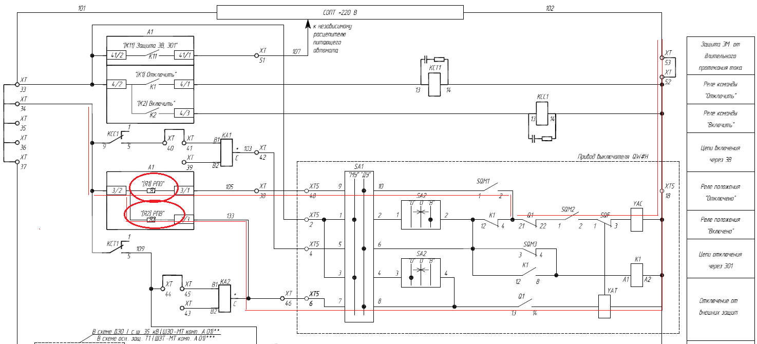
Fig. 1. Wiring diagram for 35 kV vacuum circuit breaker drive (example)
And here is another circuit, this time for a 110 kV circuit breaker.
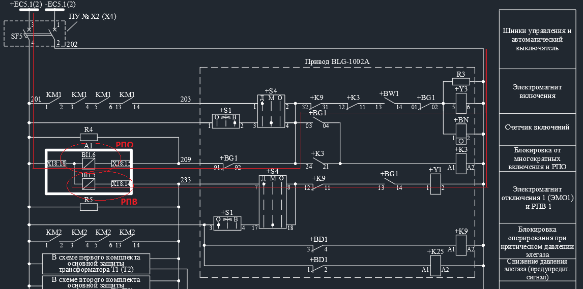
Fig. 2. Wiring diagram for 110 kV SF6 circuit breaker drive (example)
As you can see, the power to the coils of these relays (especially the RPO) is supplied through sufficiently long chains that include other contacts and electromagnets for switching off.
Naturally, these chains contain auxiliary contacts of the switch, but not only them. In general, this can include a spring charging control switch, contacts of an SF6 gas pressure monitor (blocking stage), etc. That is why the RPV and RPO relays cannot signal the current position of the switch.
What, then, do RPO and RPV “show”?
They indicate that the drive is ready for operation:
RPO - readiness for turn-on operation,
RPV - readiness for shutdown operation.
Let's take a look at the switching circuit on Fig. 1, which includes the RPO. In addition to the auxiliary contact of the Q1 switch and the YAC closing coil, it includes the following elements:
- Switch SA1 in the drive cabinet, which transfers the drive to remote or local (repair) control. To power the RPO input, the switch must be in the remote position, otherwise the signal will not pass.
- Contacts for monitoring the state of the spring of the actuator SQM1 and SQM2, which close when the spring is charged, i.e. when the switch is ready for closing operation. After each close, the actuator spring is discharged and the SQM contacts open, blocking the close command until the spring is charged.
- Contact SQF, which breaks the closing circuit if there is a parallel opening command of the circuit breaker so that there is no multiple closing effect.
If at least one of these elements is in the open state, then the RPO circuit will not collect, even if the switch is in the open position (Q1 is closed). The combination of all these elements indicates the readiness / unavailability of the circuit breaker for closing operation.
If the circuit breaker is SF6, then the contacts of the SF6 pressure switch are added to the on and off circuit, which completely blocks the control in case of a critical drop in pressure. This prevents the breaker from failing during a short circuit due to the impossibility of extinguishing the arc (no SF6 - no extinguishing medium). Such a relay can be seen on Fig. 2 (+ K9)
Also, the relay / inputs of the RPO or RPV will not be energized when the on and off circuits are broken or the power supply is turned off. When both signals RPV and RPO disappear, the relay protection device issues a warning signal to the duty officer at the substation or in the ACS.
Initially, these relays were used to control the integrity of the circuit breaker control circuits.
Features of the use of RPV and RPO signals in logic circuits
Processing of signals RPO, RPV must be carried out taking into account the logic of their formation.
For example, the RPO signal may disappear while the spring is being charged, especially in the cycle of unsuccessful automatic reclosure (operation O-tapv-VO), when a stable short-circuit is disconnected again, but the closing spring has not yet had time to charge.
Spring start-up time can reach 15 s (VVU-SESH-P-10) and more, especially with a reduced operating current voltage.
This means that it is imperative to signal the breakage of the drive circuits (simultaneous disappearance of the RPO and RPV) with a time delay of at least the spring charging time.
RPV signals are also widely used in protection and automation algorithms. For example, RPV is usually used when starting automatic reclosing, and RPO when accelerating protection.
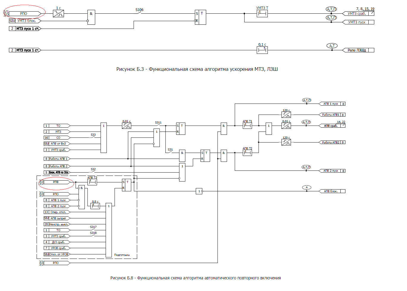
Rice. 3. Use of RPV and RPO in MP RPA algorithms (for example BMRZ-152-KL, taken from the site http://mtrele.ru)
In addition, you need to understand that even if all auxiliary contacts are closed, it is still incorrect to judge the position of the breaker by the RPO and RPV, because in this case the RPO and RPV signals disappear faster than the complete on / off operation occurs.
For example, the RPV signal ( Fig. 1) will disappear at the digital input of terminal A1 immediately, as soon as the command is issued to turn off the relay contact KCT1. Those. the switch has not yet had time to turn off (it is still on), and the RPV signal has already disappeared (the RPV input is bypassed by the relay contact KCT1).
The difference here is, of course, small (tens of milliseconds), but for such systems as RAS and ACS it can be significant. Therefore, for them, the position of the switch must be “taken” through the “dry” auxiliary contacts of the switch, when powered from the support of the corresponding system.
It is the block-contact of the switch with that shows its current position, and the RPV and RPO are the relay for monitoring the readiness of the switch for the corresponding operation.
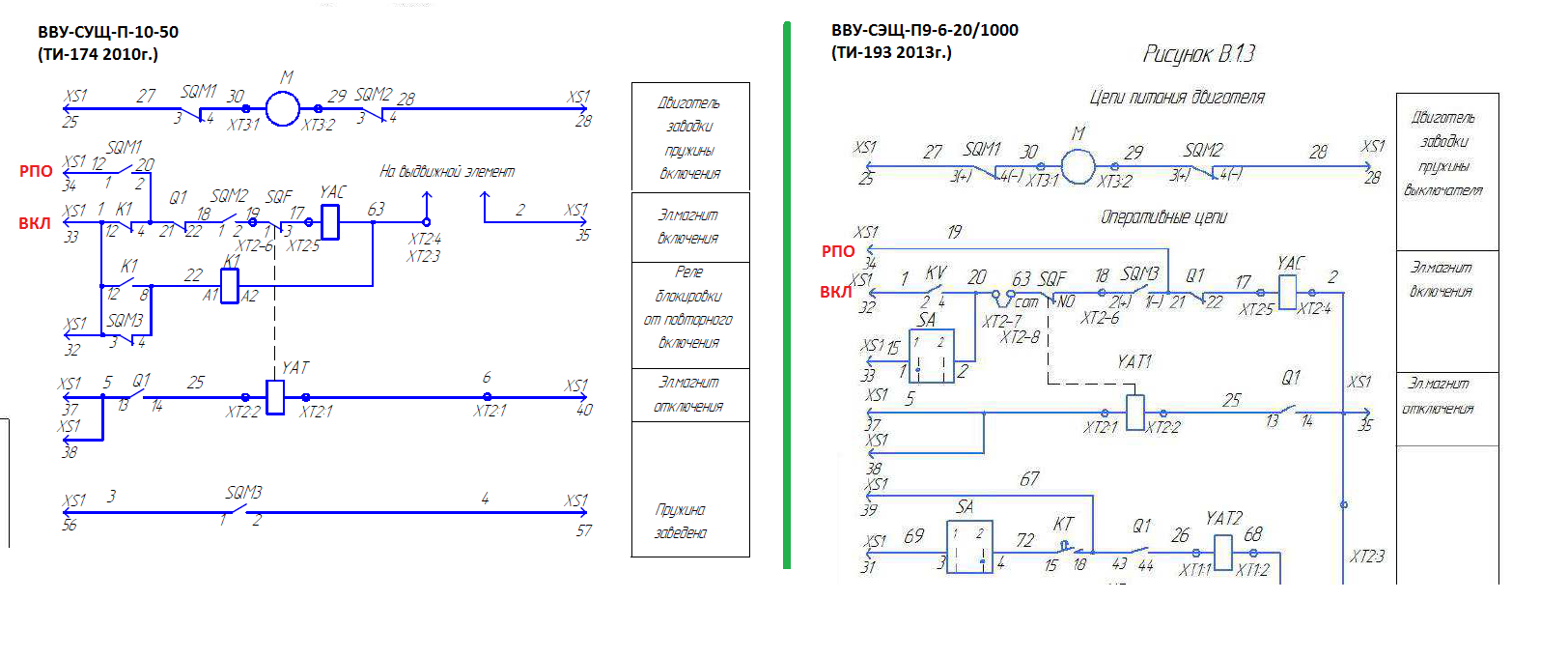
Well, and finally, a little observation
Recently, designers and manufacturers of switches have been trying to move the RPO circuit as far as possible to the closing electromagnet, bypassing the entire complex chain of auxiliary contacts.
On Rice. 4 shows two diagrams for drives of the same type of switches VVU-SESH-P with a difference of 3 years. On the left, you see a diagram from 2010, and on the right, a more modern one. Pay attention to the RPO chain - this is what I was talking about. In the first case, you control almost the entire switching circuit, and in the second only the Q1-YAC section.